Nissan Qashqai J11. Manual - part 42


  Index      Nissan     Nissan Qashqai J11 - Service and Repair Manual


Search            


Content   ..  40  41  42  43   ..


Nissan Qashqai J11. Manual - part 42


CYLINDER BLOCK

EM-107

< UNIT DISASSEMBLY AND ASSEMBLY >

[HRA2DDT]

C

D

E

F

G

H

I

J

K

L

M

A

EM

N

P

O

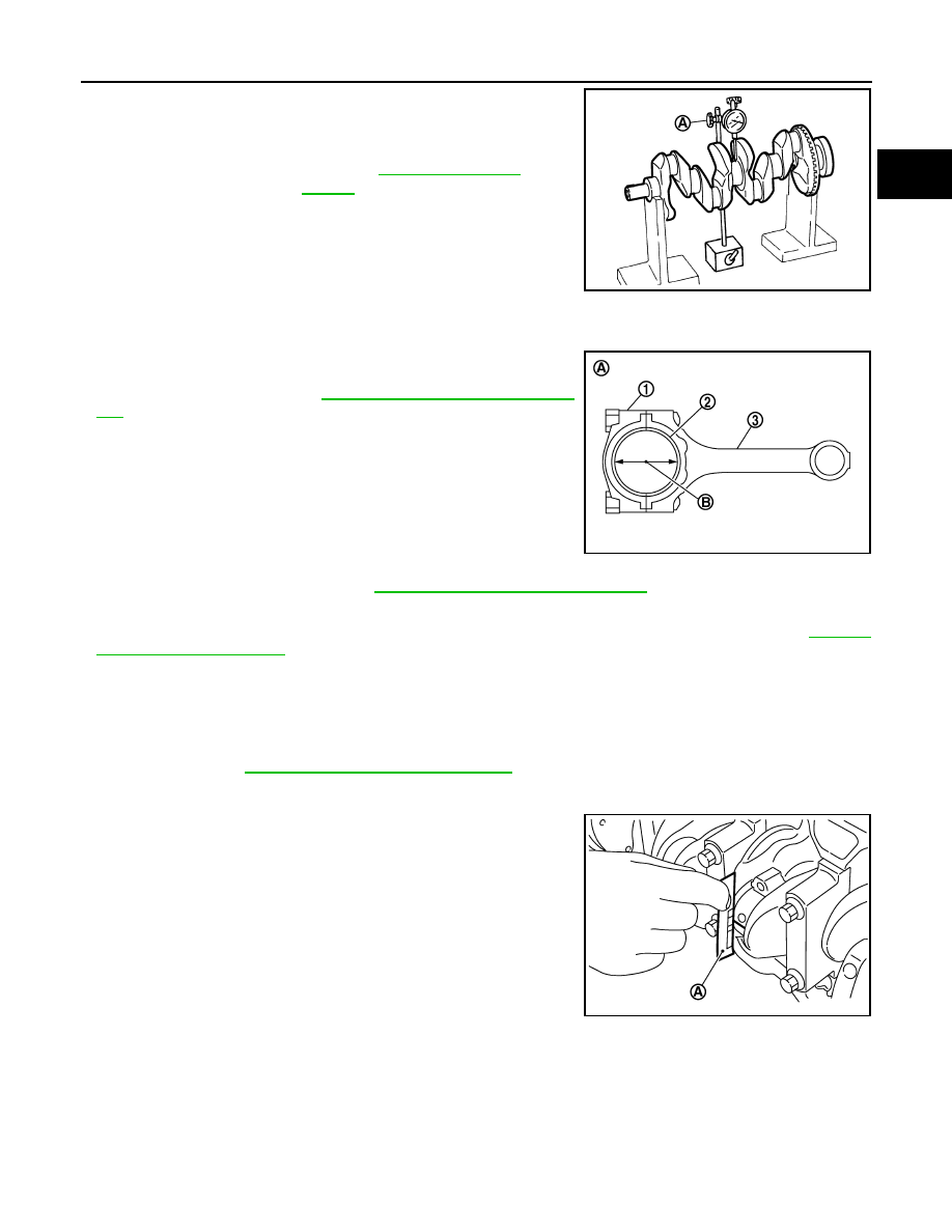
• Place a dial indicator (A) straight up on the No. 3 journal. 
• While rotating crankshaft, read the movement of the pointer on the

dial indicator. (Total indicator reading)

• If it exceeds the limit, replace crankshaft.

CONNECTING ROD BEARING OIL CLEARANCE

Method by Calculation

• Install connecting rod bearings (2) to connecting rod (3) and con-

necting rod bearing cap (1), and tighten connecting rod cap bolts to
the specified torque. Refer to 

EM-93, "Disassembly and Assem-

bly"

• Measure the inner diameter of connecting rod bearing with an

inside micrometer.
(Bearing oil clearance) = (Connecting rod bearing inner diameter)
– (Crankshaft pin journal diameter)

• If clearance exceeds the limit, select proper connecting rod bearing according to connecting rod big end

diameter and crankshaft pin journal diameter to obtain specified bearing oil clearance. Refer to 

EM-121,

"Connecting Rod Bearing"

.

Method of Using Plastigage

• Remove engine oil and dust on crankshaft pin and the surfaces of each bearing completely. 
• Cut a plastigage slightly shorter than the bearing width, and place it in crankshaft axial direction, avoiding oil

holes.

• Install connecting rod bearings to connecting rod and cap, and tighten connecting rod cap bolts to the speci-

fied torque. Refer to 

EM-93, "Disassembly and Assembly"

.

CAUTION:

Never rotate crankshaft.

• Remove connecting rod cap and bearing, and using the scale (A)

on the plastigage bag, measure the plastigage width. 
NOTE:
The procedure when the measured value exceeds the limit is
same as that described in the “Method by Calculation”.

MAIN BEARING OIL CLEARANCE

Method by Calculation

Standard and Limit

: Refer to 

EM-118, "Cylinder 

Block"

.

PBIC3458J

A

: Example

B

: Inner diameter measuring direction

Standard and Limit 

:  Refer  to 

EM-121, "Connecting Rod Bearing"

.

PBIC3275J

PBIC3276J

EM-108

< UNIT DISASSEMBLY AND ASSEMBLY >

[HRA2DDT]

CYLINDER BLOCK

• Install main bearings (3) to cylinder block (1) and main bearing cap

(2), and tighten main bearing cap mounting bolts to the specified
torque. Refer to 

EM-93, "Disassembly and Assembly"

• Measure the inner diameter of main bearing with a bore gauge.
(Bearing oil clearance) = (Main bearing inner diameter) – (Crank-
shaft main journal diameter)

• If clearance exceeds the limit, select proper main bearing according to main bearing inner diameter and

crankshaft main journal diameter to obtain specified bearing oil clearance. Refer to 

EM-121, "Main Bearing"

.

Method of Using Plastigage

• Remove engine oil and dust on crankshaft main journal and the surfaces of each bearing completely. 
• Cut a plastigage slightly shorter than the bearing width, and place it in crankshaft axial direction, avoiding oil

holes.

• Install main bearings to cylinder block and main bearing cap, and tighten main bearing cap mounting bolts to

the specified torque. Refer to 

EM-93, "Disassembly and Assembly"

CAUTION:

Never rotate crankshaft.

• Remove main bearing cap and bearings, and using the scale (A)

on the plastigage bag, measure the plastigage width. 
NOTE:
The procedure when the measured value exceeds the limit is
same as that described in the “Method by Calculation”.

MAIN BEARING CRUSH HEIGHT 

• When main bearing cap is removed after being tightened to the

specified torque with main bearings (1) installed, the tip end of
bearing must protrude (B). Refer to 

EM-93, "Disassembly and

Assembly"

.

• If the standard is not met, replace main bearings.

CONNECTING ROD BEARING CRUSH HEIGHT

• When connecting rod cap is removed after being tightened to the

specified torque with connecting rod bearings (1) installed, the tip
end of bearing must protrude (B). Refer to 

EM-93, "Disassembly

and Assembly"

.

• If the standard is not met, replace connecting rod bearings.

A

: Example

B

: Inner diameter measuring direction

Standard and Limit

: Refer to 

EM-121, "Main Bearing"

.

PBIC3277J

PBIC3278J

A

: Example

Standard

: There must be crush height.

PBIC3279J

A

: Example

Standard

: There must be crush height.

PBIC3279J

CYLINDER BLOCK

EM-109

< UNIT DISASSEMBLY AND ASSEMBLY >

[HRA2DDT]

C

D

E

F

G

H

I

J

K

L

M

A

EM

N

P

O

CLOGGED OR DAMAGED OIL FILTER (FOR INTAKE VALVE TIMING CONTROL)

• Check that there is no foreign material on the oil filter and check it

for clogging.

- Clean it if necessary.
• Check the oil filter for damage.
- Replace it if necessary.

PBIC3273J

EM-110

< UNIT DISASSEMBLY AND ASSEMBLY >

[HRA2DDT]

HOW TO SELECT PISTON AND BEARING

HOW TO SELECT PISTON AND BEARING

Description

INFOID:0000000010282253

• The identification grade stamped on each part is the grade for the dimension measured in new condition.

This grade cannot apply to reused parts. 

• For reused or repaired parts, measure the dimension accurately. Determine the grade by comparing the

measurement with the values of each selection table.

• For details of the measurement method of each part, the reuse standards and the selection method of the

selective fitting parts, refer to the text.

Connecting Rod Bearing

INFOID:0000000010282254

WHEN NEW CONNECTING ROD AND CRANKSHAFT ARE USED

1.

Apply connecting rod big end diameter grade stamped (C) on
connecting rod side face to the row in the “Connecting Rod
Bearing Selection Table”.

2.

Apply crankshaft pin journal diameter grade stamped (B) on
crankshaft front side to the column in the “Connecting Rod Bear-
ing Selection Table”.

3.

Read the symbol at the cross point of selected row and column in the “Connecting Rod Bearing Selection
Table”.

4.

Apply the symbol obtained to the “Connecting Rod Bearing Grade Table” to select connecting rod bearing.

WHEN CONNECTING ROD AND CRANKSHAFT ARE REUSED

1.

Measure the dimensions of the connecting rod big end diameter and crankshaft pin journal diameter indi-
vidually. Refer to 

EM-102, "Inspection"

.

Selection points

Selection parts 

Selection items

Selection methods

Between cylinder block and 
crankshaft

Main bearing

Main bearing grade (bearing 
thickness)

Determined by match of cylin-
der block bearing housing 
grade (inner diameter of hous-
ing) and crankshaft journal 
grade (outer diameter of jour-
nal)

Between crankshaft and con-
necting rod

Connecting rod bearing

Connecting rod bearing grade 
(bearing thickness)

Combining service grades for 
connecting rod big end diame-
ter and crankshaft pin outer di-
ameter determine connecting 
rod bearing selection.

A

: Oil hole

B

: Cylinder number

D

: Front mark

PBIC3756E

A

: Main journal diameter grade (No. 1 to 5 from left)

B

: Crankshaft pin journal diameter grade (No. 1 to 4 from left)

PBIC3757E


Content   ..  40  41  42  43   ..