Nissan Juke F15. Manual - part 987


  Index      Nissan     Nissan Juke F15 (2015 year) - Service and Repair Manual


Search            


Content   ..  985  986  987  988   ..


Nissan Juke F15. Manual - part 987


MA-40

< PERIODIC MAINTENANCE >

CHASSIS MAINTENANCE

TRANSFER OIL : Refilling

INFOID:0000000012200226

1. Remove filler plug (1) and gasket. Then fill oil up to mounting

hole for the filler plug.

CAUTION:

Carefully fill the oil. (Fill up for approximately 3 minutes.)

2. Leave the vehicle for 3 minutes, and check the oil level again.
3. Before installing filler plug, set a new gasket. Install filler plug on transfer and tighten to the specified

torque. Refer to 

DLN-116, "Exploded View"

.

CAUTION:

Never reuse gasket.

REAR PROPELLER SHAFT
REAR PROPELLER SHAFT : Inspection

INFOID:0000000012200227

APPEARANCE AND NOISE

• Check the propeller shaft tube surface for dents or cracks. If damaged, replace propeller shaft assembly.

• If center bearing is noisy or damaged, replace propeller shaft assembly.

VIBRATION

If vibration is present at high speed, inspect propeller shaft runout first.
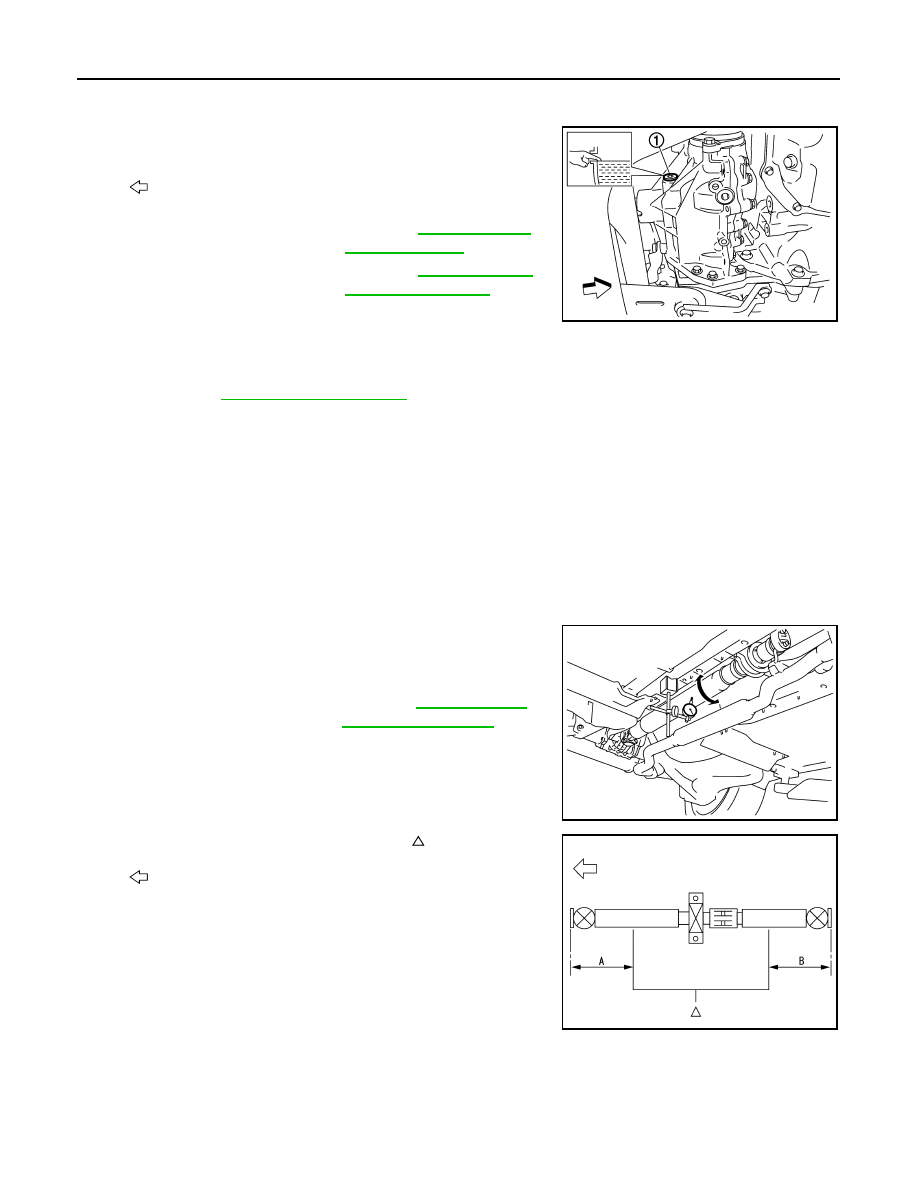
1. With a dial indicator, measure propeller shaft runout at runout

measuring points by rotating final drive companion flange with

hands.

• Propeller shaft runout measuring point (Point “ ”)

2. If runout still exceeds specifications, separate propeller shaft at

final drive companion flange or transfer companion flange; then

change the phase between companion flange and propeller

shaft by the one bolt hole at a time and install propeller shaft.

3. Check runout again. If runout still exceeds specifications,

replace propeller shaft assembly.

4. Check the vibration by driving vehicle.

REAR DIFFERENTIAL GEAR OIL

: Vehicle front

Oil and viscosity

: Refer to 

MA-11, "Fluids 

and Lubricants"

.

Oil capacity

: Refer to 

DLN-120, "Gen-

eral Specifications"

.

JSDIA2080ZZ

Propeller shaft runout

: Refer to 

DLN-128, "Pro-

peller Shaft Runout"

.

JPDID0419ZZ

: Front

Dimension

A: 542 mm (21.34 in)
B: 516.5 mm (20.33 in)

JSDIA2286ZZ

CHASSIS MAINTENANCE

MA-41

< PERIODIC MAINTENANCE >

C

D

E

F

G

H

I

J

K

L

M

B

MA

N

O

A

REAR DIFFERENTIAL GEAR OIL : Inspection

INFOID:0000000012200228

OIL LEAKAGE

Check rear final drive surrounding area (oil seal, drain plug, filler plug, and gear carrier, etc.) for oil leakage.

OIL LEVEL

1. Remove filler plug (1) and check oil level from filler plug mount-

ing hole as shown in the figure.

CAUTION:

Never start engine while checking oil level.

2. Set a new gasket on filler plug and install it on final drive assem-

bly. Refer to 

DLN-158, "Exploded View"

.

CAUTION:

Never reuse gasket.

REAR DIFFERENTIAL GEAR OIL : Draining

INFOID:0000000012200229

1. Stop engine.
2. Remove drain plug (1) and drain gear oil.
3. Set a new gasket on drain plug and install it to final drive assem-

bly and tighten to the specified torque. Refer to 

DLN-158,

"Exploded View"

.

CAUTION:

Never reuse gasket.

REAR DIFFERENTIAL GEAR OIL : Refilling

INFOID:0000000012200230

1. Remove filler plug (1). Fill with new gear oil until oil level reaches

the specified level near filler plug mounting hole.

2. After refilling oil, check oil level. Set a new gasket to filler plug,

then install it to final drive assembly. Refer to 

DLN-158,

"Exploded View"

.

CAUTION:

Never reuse gasket.

WHEELS (BONDING WEIGHT TYPE)
WHEELS (BONDING WEIGHT TYPE) : Wheel Balance Adjustment

INFOID:0000000012200231

PREPARATION BEFORE ADJUSTMENT

Using releasing agent, remove double-faced adhesive tape from the road wheel.

CAUTION:

• Be careful not to scratch the road wheel during removal.

• After removing double-faced adhesive tape, wipe clean traces of releasing agent from the road

wheel.

JSDIA2113ZZ

JSDIA2114ZZ

Oil grade and viscosity

: Refer to 

MA-11, "Fluids 

and Lubricants"

.

Oil capacity

: Refer to 

DLN-175, "Gen-

eral Specification"

.

JSDIA2113ZZ

MA-42

< PERIODIC MAINTENANCE >

CHASSIS MAINTENANCE

ADJUSTMENT

• The details of the adjustment procedure are different for each model of wheel balancer. Therefore, refer to

each instruction manual. 

• If a tire balance machine has adhesion balance weight mode settings and drive-in weight mode setting,

select and adjust a drive-in weight mode suitable for aluminum wheels.

1. Set road wheel on tire balance machine using the center hole as a guide. Start the tire balance machine.
2. When inner and outer unbalance values are shown on the tire balance machine indicator, multiply outer

unbalance value by 5/3 to determine balance weight that should be used. Select the outer balance weight

with a value closest to the calculated value above and install to the designated outer position of, or at the

designated angle in relation to the road wheel.

CAUTION:

• Never install the inner balance weight before installing the outer balance weight.

• Before installing the balance weight, always to clean the mating surface of the road wheel.

a. Indicated unbalance value 

× 5/3 = balance weight to be installed

Calculation example:

23 g (0.81 oz) 

× 5/3 = 38.33 g (1.35 oz) ⇒ 40 g (1.41 oz) bal-

ance weight (closer to calculated balance weight value)

NOTE:

Note that balance weight value must be closer to the calculated

balance weight value.

Example:

37.4 

⇒ 35 g (1.23 oz)

37.5 

⇒ 40 g (1.41 oz)

b. Installed balance weight in the position.

• When installing balance weight (1) to road wheels, set it into

the grooved area (A) on the inner wall of the road wheel as

shown in the figure so that the balance weight center (B) is

aligned with the tire balance machine indication position

(angle) (C).

CAUTION:

• Always use genuine NISSAN balance weights.

• Balance weights are non-reusable; always replace with

new ones.

• Never install three or more sheets of balance weight.

SMA054D

JPEIC0040ZZ

CHASSIS MAINTENANCE

MA-43

< PERIODIC MAINTENANCE >

C

D

E

F

G

H

I

J

K

L

M

B

MA

N

O

A

c. If calculated balance weight value exceeds 50 g (1.76 oz), install

two balance weight sheets in line with each other as shown in

the figure.

CAUTION:

Never install one balance weight sheet on top of another.

3. Start the tire balance machine again.
4. Install drive-in balance weight on inner side of road wheel in the

tire balance machine indication position (angle).

CAUTION:

Never install three or more balance weight.

5. Start the tire balance machine. Check that the inner and outer

residual unbalance value is within the allowable unbalance

value.

CAUTION:

If either residual unbalance value exceeds limit, repeat installation procedures.

WHEELS (BONDING WEIGHT TYPE) : Tire Rotation

INFOID:0000000012200232

• Follow the maintenance schedule for tire rotation service intervals.

Refer to 

MA-5, "Explanation of General Maintenance"

.

• When installing the wheel, tighten wheel nuts to the specified

torque. Refer to 

WT-39, "Exploded View"

.

CAUTION:

• Never include the T-type spare tire when rotating the tires.

• When installing wheels, tighten them diagonally by dividing

the work two to three times in order to prevent the wheels

from developing any distortion.

• Be careful not to tighten wheel nut at torque exceeding the

criteria.

• Use NISSAN genuine wheel nut.

• Perform the ID registration, after tire rotation. Refer to 

WT-20, "Work Procedure"

.

BRAKE FLUID LEVEL AND LEAKS
BRAKE FLUID LEVEL AND LEAKS : Inspection

INFOID:0000000012200233

• If fluid level is extremely low, check brake system for leaks.

BRAKE LINES AND CABLES

Allowable unbalance value
Dynamic (At flange)

: Refer to 

WT-47, "Road Wheel"

.

Static (At flange)

: Refer to 

WT-47, "Road Wheel"

.

PEIA0033E

SMA829C

SBR451D


Content   ..  985  986  987  988   ..