Nissan Juke F15. Manual - part 959


  Index      Nissan     Nissan Juke F15 (2015 year) - Service and Repair Manual


Search            


Content   ..  957  958  959  960   ..


Nissan Juke F15. Manual - part 959


LAN

MAIN LINE BETWEEN HVAC AND DLC CIRCUIT

LAN-173

< DTC/CIRCUIT DIAGNOSIS >

[CAN SYSTEM (TYPE 8)]

C

D

E

F

G

H

I

J

K

L

B

A

O

P

N

MAIN LINE BETWEEN HVAC AND DLC CIRCUIT

Diagnosis Procedure

INFOID:0000000012200639

1.

CHECK HARNESS CONTINUITY (OPEN CIRCUIT)

1. Turn the ignition switch OFF.

2. Disconnect the battery cable from the negative terminal.

3. Disconnect the following harness connectors.

-

ECM

-

A/C auto amp.

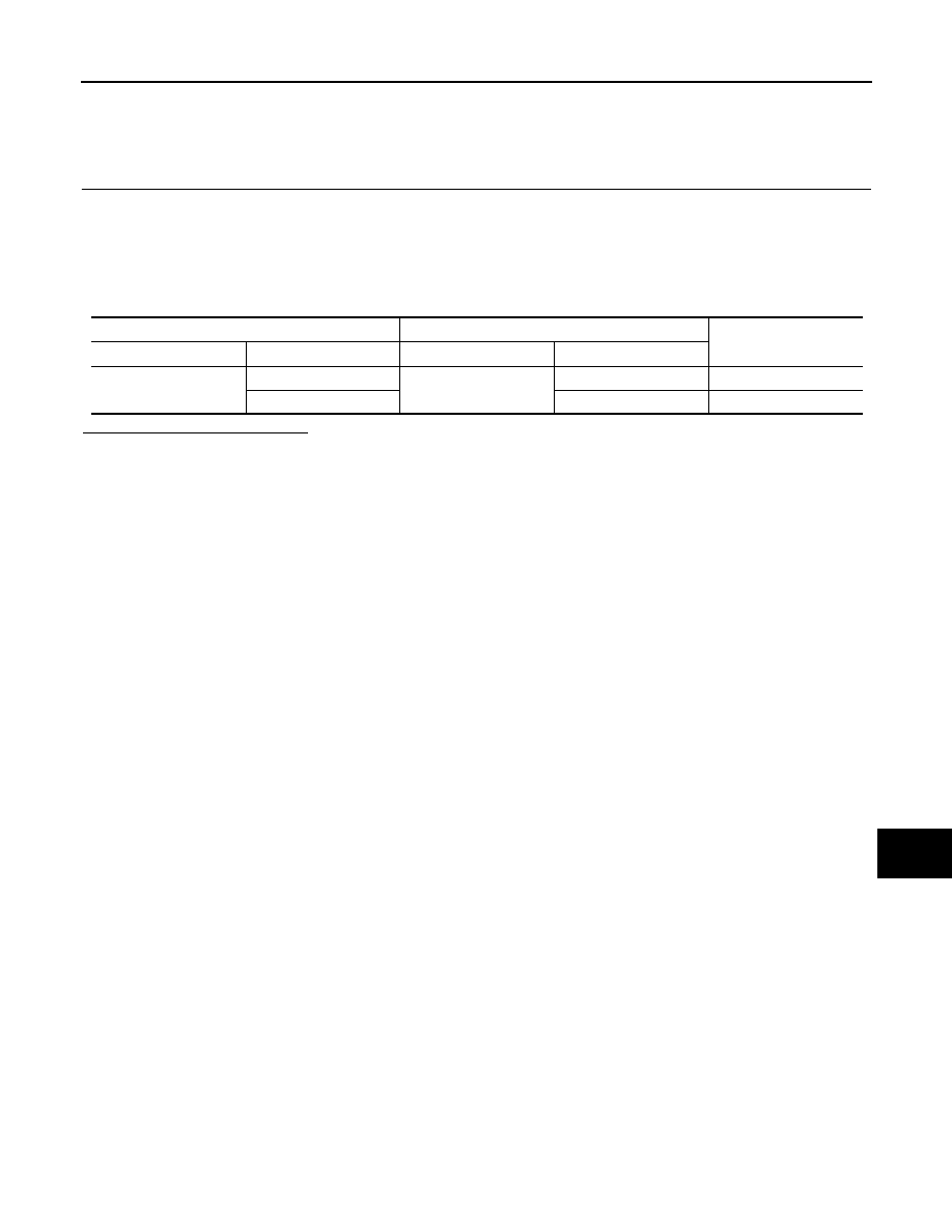
4. Check the continuity between the A/C auto amp. harness connector and the data link connector.

Is the inspection result normal?

YES (Present error)>>Check CAN system type decision again.

YES (Past error)>>Error was detected in the main line between the A/C auto amp. and the data link connec-

tor. 

NO

>> Repair the main line between the A/C auto amp. and the data link connector.

A/C auto amp. harness connector

Data link connector

Continuity

Connector No.

Terminal No.

Connector No.

Terminal No.

M50

6

M4

6

Existed

7

14

Existed

LAN-174

< DTC/CIRCUIT DIAGNOSIS >

[CAN SYSTEM (TYPE 8)]

ECM BRANCH LINE CIRCUIT

ECM BRANCH LINE CIRCUIT

Diagnosis Procedure

INFOID:0000000012200640

1.

CHECK CONNECTOR

1. Turn the ignition switch OFF.

2. Disconnect the battery cable from the negative terminal.

3. Check the terminals and connectors of the ECM for damage, bend and loose connection (unit side and

connector side).

Is the inspection result normal?

YES

>> GO TO 2.

NO

>> Repair the terminal and connector.

2.

CHECK HARNESS FOR OPEN CIRCUIT

1. Disconnect the connector of ECM.

2. Check the resistance between the ECM harness connector terminals.

-

For NISMO RS models

-

Except for NISMO RS models

Is the measurement value within the specification?

YES

>> GO TO 3.

NO

>> Repair the ECM branch line.

3.

CHECK POWER SUPPLY AND GROUND CIRCUIT

Check the power supply and the ground circuit of the ECM. Refer to the following.

• For NISMO RS models: 

EC-187, "Diagnosis Procedure"

• Except for NISMO RS models: 

EC-792, "Diagnosis Procedure"

Is the inspection result normal?

YES (Present error)>>Replace the ECM. Refer to the following.

• For NISMO RS models: 

EC-590, "Removal and Installation"

• Except for NISMO RS models: 

EC-1256, "Removal and Installation"

YES (Past error)>>Error was detected in the ECM branch line.

NO

>> Repair the power supply and the ground circuit.

ECM harness connector

Resistance (

Ω)

Connector No.

Terminal No.

E18

100

99

Approx. 108 – 132

ECM harness connector

Resistance (

Ω)

Connector No.

Terminal No.

E19

124

123

Approx. 108 – 132

LAN

4WD BRANCH LINE CIRCUIT

LAN-175

< DTC/CIRCUIT DIAGNOSIS >

[CAN SYSTEM (TYPE 8)]

C

D

E

F

G

H

I

J

K

L

B

A

O

P

N

4WD BRANCH LINE CIRCUIT

Diagnosis Procedure

INFOID:0000000012200641

1.

CHECK CONNECTOR

1. Turn the ignition switch OFF.

2. Disconnect the battery cable from the negative terminal.

3. Check the following terminals and connectors for damage, bend and loose connection (unit side and con-

nector side).

-

AWD control module

-

Harness connector B7

-

Harness connector E107

Is the inspection result normal?

YES

>> GO TO 2.

NO

>> Repair the terminal and connector.

2.

CHECK HARNESS FOR OPEN CIRCUIT

1. Disconnect the connector of AWD control module.

2. Check the resistance between the AWD control module harness connector terminals.

Is the measurement value within the specification?

YES

>> GO TO 3.

NO

>> Repair the AWD control module branch line.

3.

CHECK POWER SUPPLY AND GROUND CIRCUIT

Check the power supply and the ground circuit of the AWD control module. Refer to 

DLN-77, "Diagnosis Pro-

cedure"

.

Is the inspection result normal?

YES (Present error)>>Replace the AWD control module. Refer to 

DLN-91, "Removal and Installation"

.

YES (Past error)>>Error was detected in the AWD control module branch line.

NO

>> Repair the power supply and the ground circuit.

AWD control module harness connector

Resistance (

Ω)

Connector No.

Terminal No.

B47

4

5

Approx. 54 – 66

LAN-176

< DTC/CIRCUIT DIAGNOSIS >

[CAN SYSTEM (TYPE 8)]

ABS BRANCH LINE CIRCUIT

ABS BRANCH LINE CIRCUIT

Diagnosis Procedure

INFOID:0000000012200642

1.

CHECK CONNECTOR

1. Turn the ignition switch OFF.

2. Disconnect the battery cable from the negative terminal.

3. Check the terminals and connectors of the ABS actuator and electric unit (control unit) for damage, bend

and loose connection (unit side and connector side).

Is the inspection result normal?

YES

>> GO TO 2.

NO

>> Repair the terminal and connector.

2.

CHECK HARNESS FOR OPEN CIRCUIT

1. Disconnect the connector of ABS actuator and electric unit (control unit).

2. Check the resistance between the ABS actuator and electric unit (control unit) harness connector termi-

nals.

Is the measurement value within the specification?

YES

>> GO TO 3.

NO

>> Repair the ABS actuator and electric unit (control unit) branch line.

3.

CHECK POWER SUPPLY AND GROUND CIRCUIT

Check the power supply and the ground circuit of the ABS actuator and electric unit (control unit). Refer to

BRC-129, "Diagnosis Procedure"

.

Is the inspection result normal?

YES (Present error)>>Replace the ABS actuator and electric unit (control unit). Refer to 

BRC-153, "Removal

and Installation"

.

YES (Past error)>>Error was detected in the ABS actuator and electric unit (control unit) branch line.

NO

>> Repair the power supply and the ground circuit.

ABS actuator and electric unit (control unit) harness connector

Resistance (

Ω)

Connector No.

Terminal No.

E35

22

9

Approx. 54 – 66


Content   ..  957  958  959  960   ..