Nissan Juke F15. Manual - part 800
FL-30
< REMOVAL AND INSTALLATION >
[MR16DDT ]
EVAP CANISTER
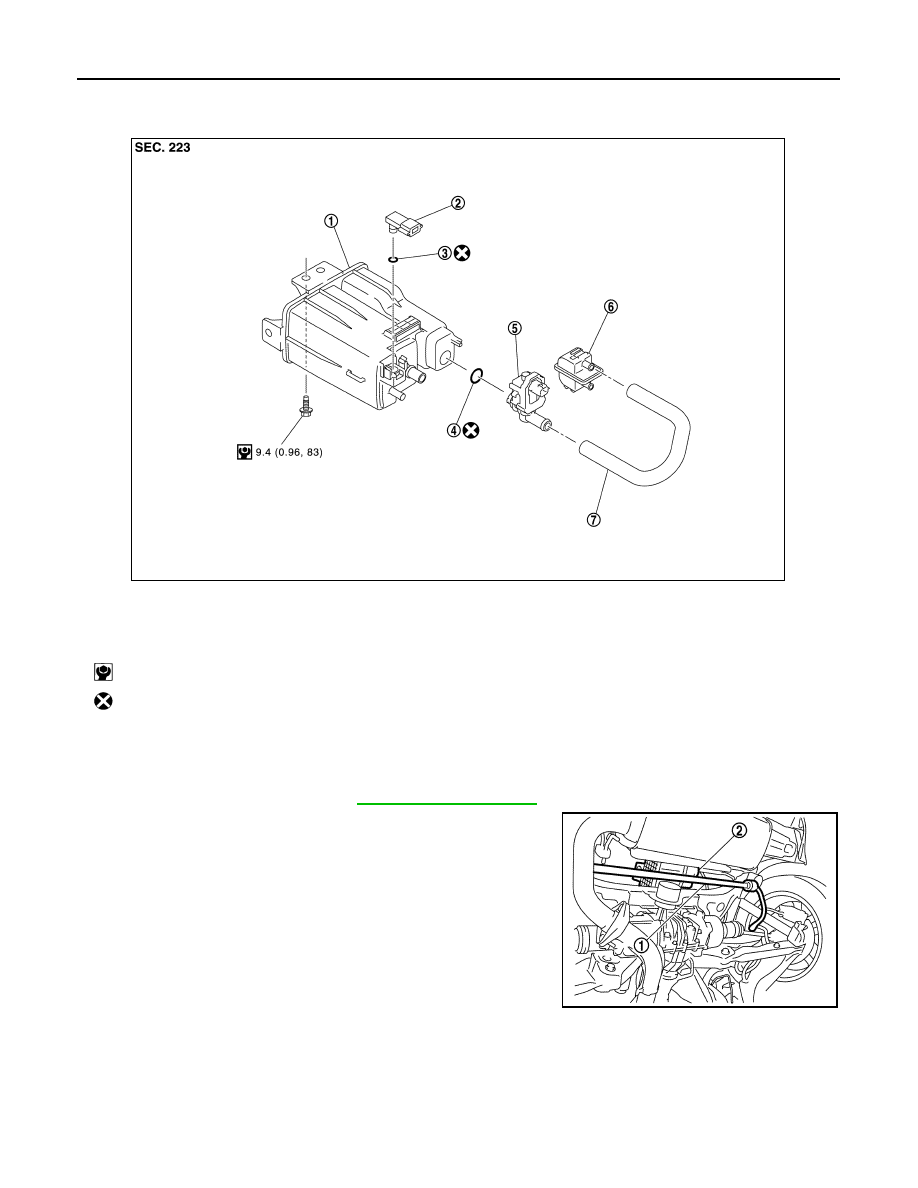
AWD : Exploded View
INFOID:0000000012197603
AWD : Removal and Installation
INFOID:0000000012197604
REMOVAL
1. Remove rear stabilizer (1). Refer to
2. Disconnect harness connectors (EVAP control pressure sensor
and EVAP canister vent control valve) and EVAP canister hoses.
3. Remove EVAP canister fixing bolt.
4. Remove EVAP canister.
NOTE:
EVAP canister vent control valve and EVAP control pressure
sensor can be removed without removing the EVAP canister.
INSTALLATION
CAUTION:
Do not reuse O-rings.
Install in the reverse order of removal.
NOTE:
Tighten EVAP canister fixing bolt to the specified torque.
1.
EVAP canister
2.
EVAP control pressure sensor
3.
O-ring
4.
O-ring
5.
EVAP canister vent control valve
6.
Canister filter
7.
EVAP canister hose
: N·m (kg-m, in-lb)
: Always replace after every disassembly.
JPBIA4878GB
2.
EVAP canister
JPBIA4329ZZ