Nissan Juke F15. Manual - part 712


  Index      Nissan     Nissan Juke F15 (2015 year) - Service and Repair Manual


Search            


Content   ..  710  711  712  713   ..


Nissan Juke F15. Manual - part 712


EXL-68

< DTC/CIRCUIT DIAGNOSIS >

[XENON TYPE]

DAYTIME RUNNING LIGHT CIRCUIT

Is the inspection result normal?

YES

>> GO TO 4.

NO

>> Repair or replace harness.

4.

CHECK DAYTIME RUNNING LIGHT GROUND CIRCUIT

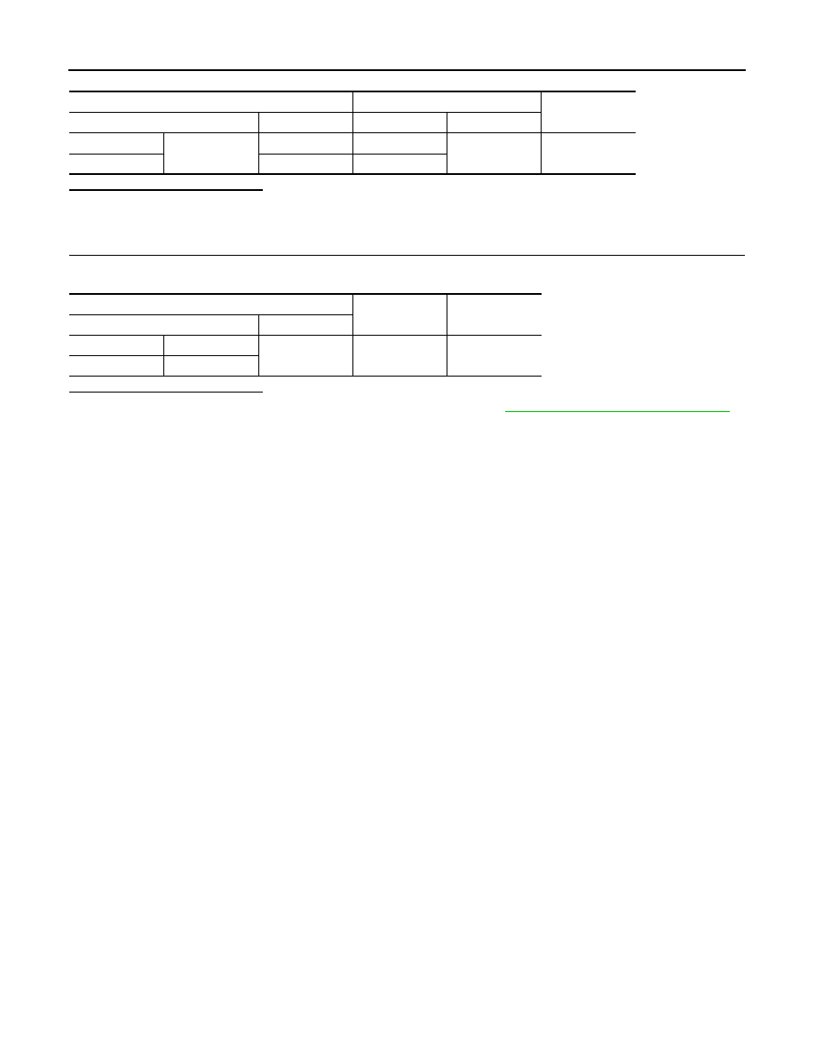
Check continuity between daytime running light harness connector and ground.

Is the inspection result normal?

YES

>> Replace the corresponding daytime running light. Refer to 

EXL-101, "Removal and Installation"

.

NO

>> Repair or replace harness.

IPDM E/R

Daytime running light

Continuity

Connector

Terminal

Connector

Terminal

RH

E12

19

E75

1

Existed

LH

20

E76

Daytime running light

Continuity

Connector

Terminal

RH

E75

2

Ground

Existed

LH

E76

FRONT FOG LAMP CIRCUIT

EXL-69

< DTC/CIRCUIT DIAGNOSIS >

[XENON TYPE]

C

D

E

F

G

H

I

J

K

M

A

B

EXL

N

O

P

FRONT FOG LAMP CIRCUIT

Component Function Check

INFOID:0000000012201655

1.

CHECK FRONT FOG LAMP OPERATION

With CONSULT

1. Select “EXTERNAL LAMPS” in “Active Test” mode of “IPDM E/R” using CONSULT.

2. With operating the test items, check that the front fog lamp is turned ON.

Without CONSULT

1. Start IPDM E/R auto active test. Refer to 

PCS-12, "Diagnosis Description"

.

2. Check that the front fog lamp is turned ON.
Is the measurement normal?

YES

>> Front fog lamp circuit is normal.

NO

>> Refer to 

EXL-69, "Diagnosis Procedure"

Diagnosis Procedure

INFOID:0000000012201656

1.

CHECK FRONT FOG LAMP FUSE

1. Turn ignition switch OFF.

2. Check that the following fuses are not blown (open).

Is the fuse blown (open)?

YES

>> Replace the blown fuse after repairing the affected circuit if a fuse is blown (open).

NO

>> GO TO 2.

2.

CHECK FRONT FOG LAMP POWER SUPPLY

With CONSULT

1. Disconnect front fog lamp connector.

2. Turn ignition switch ON.

3. Select “EXTERNAL LAMPS” in “Active Test” mode of “IPDM E/R” using CONSULT.

4. With operating the test items, check the voltage between IPDM E/R harness connector and ground.

Is the inspection result normal?

YES

>> GO TO 3.

NO

>> Replace IPDM E/R. Refer to 

PCS-37, "Removal and Installation"

.

3.

CHECK FRONT FOG LAMP POWER SUPPLY CIRCUIT

1. Turn ignition switch OFF.

2. Disconnect IPDM E/R connector.

3. Check continuity between IPDM E/R harness connector and front fog lamp harness connector.

Fog

: Front fog lamp ON

Off

: Front fog lamp OFF

Unit

Location

Fuse No.

Capacity

Front fog lamp

IPDM E/R

#50

15 A

+

-

Test item

Voltage

IPDM E/R

Connector

Terminal

RH

E12

19

Ground

EXTERNAL 
LAMPS

Fog

9 – 16 V

Off

0 – 1 V

LH

20

Fog

9 – 16 V

Off

0 – 1 V

EXL-70

< DTC/CIRCUIT DIAGNOSIS >

[XENON TYPE]

FRONT FOG LAMP CIRCUIT

Is the inspection result normal?

YES

>> GO TO 4.

NO

>> Repair or replace harness.

4.

CHECK FRONT FOG LAMP GROUND CIRCUIT

Check continuity between front fog lamp harness connector and ground.

Is the inspection result normal?

YES

>> Replace the corresponding front fog lamp bulb. Refer to 

EXL-103, "Replacement"

.

NO

>> Repair or replace harness.

IPDM E/R

Front fog lamp

Continuity

Connector

Terminal

Connector

Terminal

RH

E12

19

E48

1

Existed

LH

20

E30

Front fog lamp

Continuity

Connector

Terminal

RH

E48

2

Ground

Existed

LH

E30

TURN SIGNAL LAMP CIRCUIT

EXL-71

< DTC/CIRCUIT DIAGNOSIS >

[XENON TYPE]

C

D

E

F

G

H

I

J

K

M

A

B

EXL

N

O

P

TURN SIGNAL LAMP CIRCUIT

Component Function Check

INFOID:0000000012201657

1.

CHECK TURN SIGNAL LAMP OPERATION

With CONSULT

1. Turn ignition switch ON.

2. Select “FLASHER” of “BCM” using CONSULT.

3. Select “FLASHER” in “Active Test” mode.

4. With operating the test items, check that the turn signal lamps is turned ON.

Is the inspection result normal?

YES

>> Turn signal lamp circuit is normal.

NO

>> Refer to 

EXL-71, "Diagnosis Procedure"

.

Diagnosis Procedure

INFOID:0000000012201658

1.

CHECK TURN SIGNAL LAMP POWER SUPPLY

With CONSULT

1. Turn ignition switch OFF.

2. Disconnect the following connectors.

-

Front turn signal lamp

-

Door mirror

-

Rear combination lamp

3. Turn ignition switch ON.

4. Select “FLASHER” of “BCM” using CONSULT.

5. Select “FLASHER” in “Active Test” mode.

6. With operating the test items, check voltage between BCM harness connector and ground.

Is the inspection result normal?

YES

>> GO TO 3.

NO

>> GO TO 2.

2.

CHECK TURN SIGNAL LAMP POWER SUPPLY CIRCUIT (SHORT)

1. Turn ignition switch OFF.

2. Disconnect BCM connector.

3. Check continuity between BCM harness connector and ground.

Is the inspection result normal?

RH

: Turn signal lamps (RH) ON

LH

: Turn signal lamps (LH) ON

Off

: Turn signal lamps OFF

+

-

Test item

Voltage

BCM

Connector

Terminal

RH

M69

61

Ground

FLASHER

RH

9 – 16 V

Off

0 V

LH

60

LH

9 – 16 V

Off

0 V

BCM

Continuity

Connector

Terminal

RH

M69

61

Ground

Not existed

LH

60


Content   ..  710  711  712  713   ..