Nissan Juke F15. Manual - part 701


  Index      Nissan     Nissan Juke F15 (2015 year) - Service and Repair Manual


Search            


Content   ..  699  700  701  702   ..


Nissan Juke F15. Manual - part 701


EXL-24

< SYSTEM DESCRIPTION >

[XENON TYPE]

DIAGNOSIS SYSTEM (BCM)

*: For models without panic alarm function, this item cannot be used.
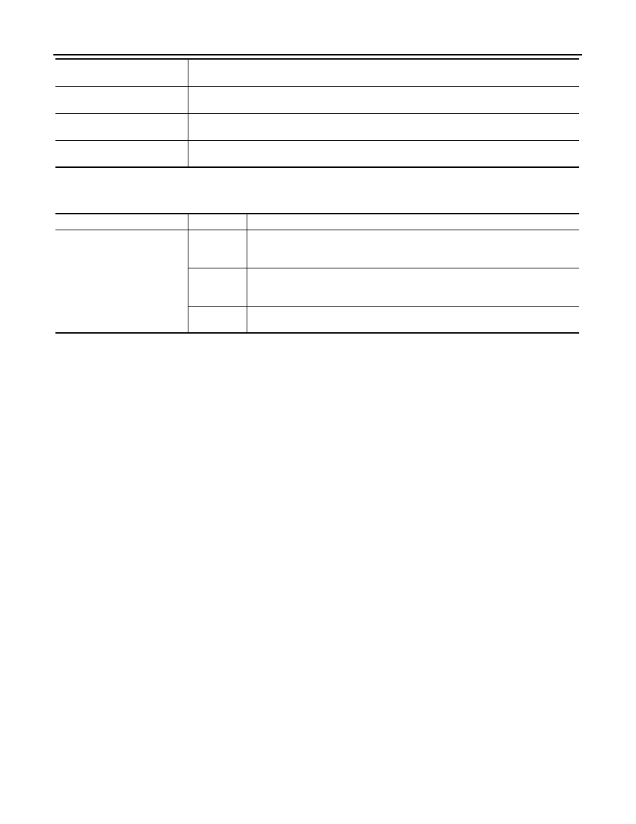
ACTIVE TEST

RKE-LOCK
[On/Off]

Indicates [On/Off] condition of LOCK signal from Intelligent Key

RKE-UNLOCK
[On/Off]

Indicates [On/Off] condition of UNLOCK signal from Intelligent Key

RKE-PANIC*
[On/Off]

Indicates [On/Off] condition of PANIC button of Intelligent Key

Monitor item

[Unit]

Description

Test item

Operation

Description

FLASHER

RH

• Outputs voltage to turn the right side turn signal lamps ON
• Transmits the turn indicator signal to combination meter via CAN communication 

to turn the turn signal indicator lamp (RH) ON

LH

• Outputs voltage to turn the left side turn signal lamps ON
• Transmits the turn indicator signal to combination meter via CAN communication 

to turn the turn signal indicator lamp (LH) ON

Off

• Stops the voltage to turn the turn signal lamps OFF
• Stops the turn indicator signal transmission

DIAGNOSIS SYSTEM (IPDM E/R)

EXL-25

< SYSTEM DESCRIPTION >

[XENON TYPE]

C

D

E

F

G

H

I

J

K

M

A

B

EXL

N

O

P

DIAGNOSIS SYSTEM (IPDM E/R)

Diagnosis Description

INFOID:0000000012962263

AUTO ACTIVE TEST

Description

In auto active test mode, the IPDM E/R sends a drive signal to the following systems to check their operation.

• Rear window defogger

• Front wiper motor

• Parking lamp

• License plate lamp

• Tail lamp

• Side marker lamp

• Front fog lamp

• Headlamp (LO, HI)

• A/C compressor (magnet clutch)

• Cooling fan

Operation Procedure

CAUTION:

Wiper arm interferes with hood when wiper is operated while wiper arm is in the raised position.

Always perform auto active test without setting wiper arm in the raised position. Always pour water on

front windshield glass in advance to auto active test so that damage on front windshield glass surface

is prevented.
1. Turn the ignition switch OFF.
2. Turn the ignition switch ON, and within 20 seconds, press the driver door switch 10 times. Then turn the

ignition switch OFF.

CAUTION:

Close passenger door.

3. Turn the ignition switch ON within 10 seconds. After that the horn sounds once and the auto active test

starts.

CAUTION:

Engine starts when ignition switch is turned ON while brake pedal is depressed.

4. After a series of the following operations is repeated 3 times, auto active test is completed.
NOTE:

• When auto active test mode has to be cancelled halfway through test, turn the ignition switch OFF.

• When auto active test is not activated, door switch may be the cause. Check door switch. Refer to 

DLK-77,

"Component Function Check"

.

Inspection in Auto Active Test Mode

When auto active test mode is actuated, the following operation sequence is repeated 3 times.

Operation 
sequence

Inspection location

Operation

1

Rear window defogger

10 seconds

2

Front wiper motor

LO for 5 seconds 

→ HI for 5 seconds

3

• Parking  lamp
• License plate lamp
• Tail lamp
• Side marker lamp
• Front fog lamp

10 seconds

4

Headlamp

LO for 10 seconds 

→HI ON ⇔ OFF 5 times

5

A/C compressor (magnet clutch) ON 

⇔ OFF 5 times

6

Cooling fan

50% duty for 5 seconds 

→ 100% duty for 5 seconds

EXL-26

< SYSTEM DESCRIPTION >

[XENON TYPE]

DIAGNOSIS SYSTEM (IPDM E/R)

Concept of auto active test

• IPDM E/R starts the auto active test with the door switch signals transmitted by BCM via CAN communica-

tion. Therefore, the CAN communication line between IPDM E/R and BCM is considered normal if the auto

active test starts successfully.

• The auto active test facilitates troubleshooting if any systems controlled by IPDM E/R cannot be operated.

Diagnosis chart in auto active test mode

JMMIA0588GB

Symptom

Inspection contents

Possible cause

Rear window defogger does not operate

Perform auto active test.
Does the rear window defog-
ger operate?

YES

BCM signal input circuit

NO

• Rear window defogger
• Rear window defogger ground circuit
• Harness or connector between IPDM E/R 

and rear window defogger

• IPDM E/R

Any of the following components do not 
operate

• Parking  lamp
• License plate lamp
• Tail lamp
• Side marker lamp
• Front fog lamp
• Headlamp (HI, LO)
• Front wiper motor

Perform auto active test.
Does the applicable system 
operate?

YES

BCM signal input circuit

NO

• Lamp or motor
• Lamp or motor ground circuit
• Harness or connector between IPDM E/R 

and applicable system

• IPDM E/R

A/C compressor does not operate

Perform auto active test.
Does the magnet clutch oper-
ate?

YES

• A/C amp. signal input circuit
• CAN communication signal between A/C 

amp. and ECM

• CAN communication signal between ECM 

and IPDM E/R

NO

• Magnet clutch
• Harness or connector between IPDM E/R 

and magnet clutch

• IPDM E/R

DIAGNOSIS SYSTEM (IPDM E/R)

EXL-27

< SYSTEM DESCRIPTION >

[XENON TYPE]

C

D

E

F

G

H

I

J

K

M

A

B

EXL

N

O

P

CONSULT Function (IPDM E/R)

INFOID:0000000012962264

APPLICATION ITEM

CONSULT performs the following functions via CAN communication with IPDM E/R.

SELF DIAGNOSTIC RESULT

Refer to 

PCS-24, "DTC Index"

.

DATA MONITOR

NOTE:

The following table includes information (items) inapplicable to this vehicle. For information (items) applicable

to this vehicle, refer to CONSULT display items.

Cooling fan does not operate

Perform auto active test.
Does the cooling fan operate?

YES

• ECM signal input circuit
• CAN communication signal between ECM 

and IPDM E/R

NO

• Harness or connector between IPDM E/R 

and cooling fan relay

• Harness or connector between IPDM E/R 

and cooling fan control module.

• Harness or connector between cooling fan 

control module and cooling fan motor 

• Cooling fan motor
• Cooling fan relay
• Cooling fan control module
• IPDM E/R

Symptom

Inspection contents

Possible cause

Diagnosis mode

Description

Ecu Identification

Allows confirmation of IPDM E/R part number.

Self Diagnostic Result

Displays the diagnosis results judged by IPDM E/R.

Data Monitor

Displays the real-time input/output data from IPDM E/R input/output data.

Active Test

IPDM E/R can provide a drive signal to electronic components to check their operations.

CAN Diag Support Monitor

The results of transmit/receive diagnosis of CAN communication can be read.

Monitor Item

[Unit]

MAIN 

SIGNALS

Description

RAD FAN REQ
[%]

×

Displays the value of the cooling fan speed request signal received from ECM via CAN 
communication.

AC COMP REQ
[Off/On]

×

Displays the status of the A/C compressor request signal received from ECM via CAN 
communication.

TAIL&CLR REQ
[Off/On]

×

Displays the status of the position light request signal received from BCM via CAN 
communication.

HL LO REQ
[Off/On]

×

Displays the status of the low beam request signal received from BCM via CAN com-
munication.

HL HI REQ
[Off/On]

×

Displays the status of the high beam request signal received from BCM via CAN com-
munication.

FR FOG REQ
[Off/On]

×

Displays the status of the front fog light request signal received from BCM via CAN 
communication.

FR WIP REQ
[Stop/1LOW/Low/Hi]

×

Displays the status of the front wiper request signal received from BCM via CAN com-
munication.

WIP AUTO STOP
[STOP P/ACT P]

×

Displays the status of the front wiper auto stop signal judged by IPDM E/R.

WIP PROT
[Off/BLOCK]

×

Displays the status of the front wiper fail-safe operation judged by IPDM E/R.

IGN RLY1 -REQ
[Off/On]

Displays the status of the ignition switch ON signal received from BCM via CAN com-
munication.


Content   ..  699  700  701  702   ..