Nissan Juke F15. Manual - part 698


  Index      Nissan     Nissan Juke F15 (2015 year) - Service and Repair Manual


Search            


Content   ..  696  697  698  699   ..


Nissan Juke F15. Manual - part 698


EXL-12

< SYSTEM DESCRIPTION >

[XENON TYPE]

SYSTEM

- Lighting switch OFF

• IPDM E/R turns the integrated headlamp low relay ON, and turns the headlamp (LO) ON according to the

low beam request signal.

• When in any of following conditions, follow me home function can be cancelled while follow me home func-

tion is operating.

Follow me home OFF condition

- Ignition switch is turned from OFF

→ACC or ON

- Lighting switch is turned from OFF

→ON

NOTE:

• Flash-to-pass operation illumination time for 1 time can be extended to approximately 30 seconds during

operation of follow me home function.

• Flash-to-pass operation can be illuminated continuously for approximately 60 seconds (flash-to-pass opera-

tion, 2 times), approximately 90 seconds (flash-to-pass operation, 3 times), and a maximum of approxi-

mately 120 seconds (flash-to-pass operation, 4 times).

• Follow me home function activating time can be set by CONSULT. Refer to 

EXL-20, "HEADLAMP : CON-

SULT Function (BCM - HEAD LAMP) (XENON TYPE)"

.

HEADLAMP SYSTEM : Fail-Safe

INFOID:0000000012201613

CAN COMMUNICATION CONTROL

When CAN communication with BCM is impossible, IPDM E/R performs fail-safe control. After CAN communi-

cation recovers normally, it also returns to normal control.

If No CAN Communication Is Available With BCM

AUTO LIGHT SYSTEM
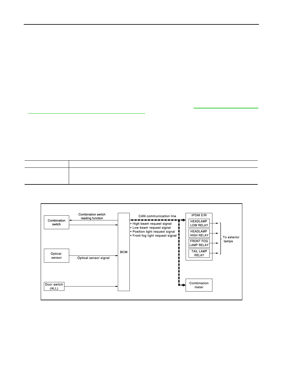
AUTO LIGHT SYSTEM : System Diagram

INFOID:0000000012201614

AUTO LIGHT SYSTEM : System Description

INFOID:0000000012201615

OUTLINE

•  Auto light system is controlled by each function of BCM and IPDM E/R.

Control by BCM

- Combination switch reading function

- Headlamp control function

Control part

Fail-safe operation

Headlamp

• Turns ON the headlamp low relay when the ignition switch is turned ON
• Turns OFF the headlamp low relay when the ignition switch is turned OFF
• Headlamp high relay OFF

JMLIA1254GB

SYSTEM

EXL-13

< SYSTEM DESCRIPTION >

[XENON TYPE]

C

D

E

F

G

H

I

J

K

M

A

B

EXL

N

O

P

- Auto light function

- Delay timer function

- Wiper linked auto lighting function

Control by IPDM E/R

- Relay control function

• Auto light system has the auto light function (with twilight lighting function), wiper linked auto lighting function

and delay timer function.

- Auto light function automatically turns ON/OFF the exterior lamps* and each illumination automatically,

depending on the outside brightness.

- Wiper linked auto lighting function automatically turns ON/OFF the exterior lamps* and each illumination

when the light switch is in the AUTO position, according to a front wiper operation.

- When auto light system turns the exterior lamps ON with the ignition switch OFF, delay timer function turns

the exterior lamps OFF, depending on the vehicle condition with the auto light function after a certain period

of time.

*: Headlamp (LO/HI), front fog lamp, parking lamp, license plate lamp, tail lamp and side marker lamp (Head-

lamp HI and front fog lamp depend on the combination switch condition.)

NOTE:

The settings of the twilight lighting function and the wiper linked auto lighting function can be changed with

CONSULT. Refer to 

EXL-20, "HEADLAMP : CONSULT Function (BCM - HEAD LAMP) (XENON TYPE)"

.

AUTO LIGHT FUNCTION (WITH TWILIGHT LIGHTING FUNCTION)

Description

• BCM detects the combination switch condition with the combination switch reading function.

• BCM supplies voltage to the optical sensor when the ignition switch is turned ON.

• Optical sensor converts outside brightness (lux) to voltage and transmits the optical sensor signal to BCM.

• BCM filters outside brightness based on the optical sensor signal and judges outside brightness.

• BCM detects change status of outside brightness according to outside brightness from the optical sensor

signal and filtered outside brightness. Based on the change status, BCM judges ON/OFF condition of the

exterior lamp.

• BCM transmits each request signal to IPDM E/R and combination meter via CAN communication, according

to ON/OFF condition by the auto light function.

NOTE:

As to ON/OFF timing, the sensitivity depends on settings. The settings can be changed with CONSULT. Refer

to 

EXL-20, "HEADLAMP : CONSULT Function (BCM - HEAD LAMP) (XENON TYPE)"

.

DELAY TIMER FUNCTION

• BCM turns the headlamp (LO) OFF depending on the vehicle condition with the auto light function when the

ignition switch is turned OFF.

- Turns the headlamp (LO) OFF 5 minutes after the ignition switch is turned OFF.

- Turns the headlamp (LO) OFF 5 minutes after detecting that any door opens. (Door switch ON).

- Turns the headlamp (LO) OFF a certain period of time* after closing all doors. (Door switch ON 

→ OFF).

• Delay timer function turns OFF, when the ignition switch is other than OFF or the lighting switch is other than

AUTO.

*: The preset time is 45 seconds. The timer operating time can be set by CONSULT. Refer to 

EXL-20, "HEAD-

LAMP : CONSULT Function (BCM - HEAD LAMP) (XENON TYPE)"

.

NOTE:

When any position other than the lighting switch AUTO is set, the auto light system function switches to the

exterior lamp battery saver function.

WIPER LINKED AUTO LIGHTING FUNCTION

BCM turns the exterior lamps ON when detecting 4 operations of the front wiper work the light switch in AUTO

position.

NOTE:

BCM turns OFF the headlamps 3 seconds after the front wiper switch is turned from ON

⇒OFF.

DAYTIME RUNNING LIGHT SYSTEM

EXL-14

< SYSTEM DESCRIPTION >

[XENON TYPE]

SYSTEM

DAYTIME RUNNING LIGHT SYSTEM : System Diagram

INFOID:0000000012201616

EXCEPT FOR NISMO MODELS

NISMO MODELS

DAYTIME RUNNING LIGHT SYSTEM : System Description

INFOID:0000000012201617

OUTLINE

Except for NISMO Models

• Turns the headlamp (HI) ON [Headlamp (HI) at approximately half illumination] as the daytime running light.

• Daytime running light is controlled by daytime running light control function and combination switch reading

function of BCM, and relay control function of IPDM E/R.

NISMO Models

Daytime running light is controlled by daytime running light control function and combination switch reading

function of BCM, and relay control function of IPDM E/R.

DAYTIME RUNNING LIGHT OPERATION 

Except for NISMO Models

• BCM detects the combination switch condition by the combination switch reading function.

• BCM detects vehicle condition depending on the following signals.

- Engine status signal (received from ECM via CAN communication)

- Parking brake switch signal (received from combination meter via CAN communication)

• BCM transmits the daytime running light request signal to IPDM E/R via CAN communication according to

the daytime running light ON condition.

Daytime running light ON condition

- Engine running with the parking brake released, and any following conditions are satisfied.

JMLIA6141GB

JMLIA3997GB

SYSTEM

EXL-15

< SYSTEM DESCRIPTION >

[XENON TYPE]

C

D

E

F

G

H

I

J

K

M

A

B

EXL

N

O

P

• Lighting switch OFF

• Lighting switch 1ST

• IPDM E/R controls the daytime running light relay (ground-side) to turn ON according to the daytime running

light request signal.

• Power is supplied from the daytime running light relay through headlamp high RH and IPDM E/R to head-

lamp high LH. And high beam headlamps are illuminated (approximately half illumination) as the daytime

running light.

NISMO Models

• BCM detects the combination switch condition by the combination switch reading function.

• BCM detects vehicle condition depending on the following signals.

- Engine status signal (received from ECM via CAN communication)

- Parking brake switch signal (received from combination meter via CAN communication)

• BCM transmits the daytime running light request signal to IPDM E/R via CAN communication according to

the daytime running light ON condition.

Daytime running light ON condition

- Engine running with the parking brake released, and any following conditions are satisfied.

• Lighting switch OFF

• Lighting switch 1ST

• IPDM E/R turns the integrated daytime running light relay ON, and turns the daytime running light ON

according to the daytime running light request signal.

TURN SIGNAL AND HAZARD WARNING LAMP SYSTEM
TURN SIGNAL AND HAZARD WARNING LAMP SYSTEM : System Diagram

INFOID:0000000012201618

TURN SIGNAL AND HAZARD WARNING LAMP SYSTEM : System Description

INFOID:0000000012201619

OUTLINE

Turn signal lamp and hazard warning lamp is controlled by combination switch reading function and the flasher

control function of BCM.

TURN SIGNAL LAMP OPERATION

• BCM detects the combination switch condition by the combination switch reading function.

• BCM supplies voltage to the right (left) turn signal lamp circuit when the ignition switch is ON and the turn

signal switch is in the right (left) position. BCM blinks the turn signal lamp.

HAZARD WARNING LAMP OPERATION

BCM supplies voltage to both turn signal lamp circuits when the hazard switch is ON. BCM blinks the hazard

warning lamp.

TURN SIGNAL INDICATOR LAMP AND TURN SIGNAL SOUND OPERATION

• BCM transmits the turn indicator signal to the combination meter using CAN communication while the turn

signal lamp and the hazard warning lamp are operating.

JMLIA3117GB


Content   ..  696  697  698  699   ..