Nissan Juke F15. Manual - part 682
EM-282
< UNIT DISASSEMBLY AND ASSEMBLY >
[MR EXCEPT FOR NISMO RS MODELS]
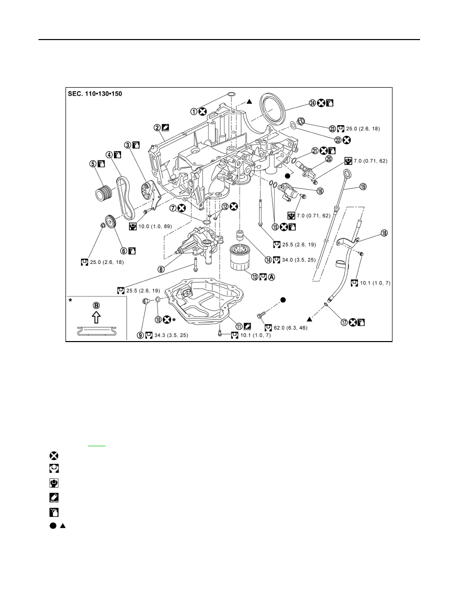
OIL PAN (UPPER)
OIL PAN (UPPER)
Exploded View
INFOID:0000000012197441
Removal and Installation
INFOID:0000000012197442
REMOVAL
1.
O-ring
2.
Oil pan (upper)
3.
Oil pump drive chain tensioner
4.
Oil pump drive chain
5.
Crankshaft sprocket
6.
Oil pump sprocket
7.
O-ring
8.
Oil pump
9.
Oil pan drain plug
10. Drain plug washer
11. Oil pan (lower)
12. O-ring
13. Oil filter
14. Oil filter stud
15. O-ring
16.
Engine oil pressure control solenoid
valve
17. O-ring
18. Oil level gauge guide
19. Oil level gauge
20. Crankshaft position sensor
21. O-ring
22. Gasket
23. Plug
24. Rear oil seal
A.
.
B.
Oil pan side
: Always replace after every disassembly.
: N·m (kg-m, ft-lb)
: N·m (kg-m, in-lb)
: Sealing point
: Should be lubricated with oil.
, : Indicates that the parts is connected at points with same symbols in actual vehicle.
JSBIA5724GB