Nissan Juke F15. Manual - part 657


  Index      Nissan     Nissan Juke F15 (2015 year) - Service and Repair Manual


Search            


Content   ..  655  656  657  658   ..


Nissan Juke F15. Manual - part 657


EM-182

< BASIC INSPECTION >

[MR EXCEPT FOR NISMO RS MODELS]

COMPRESSION PRESSURE

COMPRESSION PRESSURE

Inspection

INFOID:0000000012197368

1. Warm up engine thoroughly. Then, stop it.
2. Release fuel pressure. Refer to 

EC-771, "Work Procedure"

.

3. Remove ignition coil and spark plug from each cylinder. Refer to 

EM-214, "Exploded View"

.

4. Connect engine tachometer (not required in use of CONSULT).
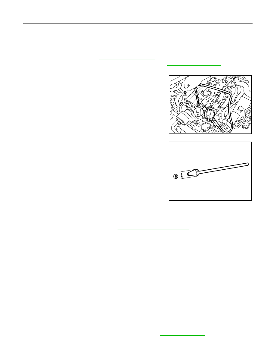
5. Install compression gauge (B) with an adapter (A) (commercial

service tool) onto spark plug hole.

• Use the adapter whose picking up end inserted to spark plug

hole is smaller than 20 mm (0.79 in) in diameter. Otherwise, it

may be caught by cylinder head during removal.

6. With accelerator pedal fully depressed, turn ignition switch to “START” for cranking. When the gauge

pointer stabilizes, read the compression pressure and the engine rpm. Perform these steps to check each

cylinder.

CAUTION:

Always use a fully charged battery to obtain the specified engine speed.

• If the engine speed is out of the specified range, check battery liquid for proper gravity. Check the

engine speed again with normal battery gravity. 

• If compression pressure is below minimum value, check valve clearances, and parts associated with

combustion chamber (valve, valve seat, piston, piston ring, cylinder bore, cylinder head, and cylinder

head gasket). After the checking, measure compression pressure again.

• If some cylinder has low compression pressure, pour small amount of engine oil into the spark plug hole

of the cylinder to recheck it for compression.

- If the added engine oil improves the compression, piston rings may be worn out or damaged. Check pis-

ton rings and replace if necessary.

- If the compression pressure remains at low level despite the addition of engine oil, valves may be mal-

functioning. Check valves for damage. Replace valve or valve seat accordingly.

• If two adjacent cylinders have respectively low compression pressure and their compression remains

low even after the addition of engine oil, cylinder head gaskets are leaking. In such a case, replace cyl-

inder head gaskets.

7. After inspection is completed, install removed parts.
8. Start the engine, and check that the engine runs smoothly.
9. Perform trouble diagnosis. If DTC appears, erase it. Refer to 

EC-785, "Description"

.

PBIC3541J

a

: 20 mm (0.79 in)

JPBIA0171ZZ

Compression pressure : Refer to 

EM-311, "General Specification"

.

NOISE, VIBRATION AND HARSHNESS (NVH) TROUBLESHOOTING

EM-183

< SYMPTOM DIAGNOSIS >

[MR EXCEPT FOR NISMO RS MODELS]

C

D

E

F

G

H

I

J

K

L

M

A

EM

N

P

O

SYMPTOM DIAGNOSIS

NOISE, VIBRATION AND HARSHNESS (NVH) TROUBLESHOOTING

Diagnosis Chart By Symptom

INFOID:0000000012197369

1. Narrow down the locations where noise is occurring.
2. Narrow down the types of noise.

JPBIA7071GB

EM-184

< SYMPTOM DIAGNOSIS >

[MR EXCEPT FOR NISMO RS MODELS]

NOISE, VIBRATION AND HARSHNESS (NVH) TROUBLESHOOTING

3. Narrow down the presumed causes from the relationship between the engine operating conditions when

the noise occurs and the symptoms.

4. Inspect the part that is presumed to be the source of the noise.
If necessary, repair or replace the specific part.

A: Closely related B: Related C: Sometimes related —: Not related

Location 

of noise

Type of 

noise

Operating condition of engine

Source of 

noise

Check item

Refer-

ence page

Before 

warm-

up

After 

warm-

up

When 

start-

ing

When 

idling

When 

racing

While 

driving

Top of en-
gine
Rocker 
cover
Cylinder 
head

Ticking or 
clicking

C

A

A

B

Tappet 
noise

Valve clearance

EM-179

Rattle

C

A

A

B

C

Camshaft 
bearing 
noise

Camshaft journal oil 
clearance
Camshaft runout

EM-264

Crank-
shaft pul-
ley
Cylinder 
block 
(Side of 
engine)
Oil pan

Slap or 
knock

A

B

B

Piston pin 
noise

Piston to piston pin oil 
clearance
Connecting rod bushing 
oil clearance

EM-294

Slap or 
rap

A

B

B

A

Piston 
slap noise

Piston to cylinder bore 
clearance
Piston ring side clear-
ance
Piston ring end gap
Connecting rod bend 
and torsion

EM-294

Knock

A

B

C

B

B

B

Connect-
ing rod 
bearing 
noise

Connecting rod bushing 
oil clearance 
Connecting rod bearing 
oil clearance

EM-294

Knock

A

B

A

B

C

Main bear-
ing noise

Main bearing oil clear-
ance
Crankshaft runout

EM-294

Front of 
engine
Front cov-
er

Tapping or 
ticking

A

A

B

B

B

Timing 
chain and 
chain ten-
sioner 
noise

Timing chain cracks 
and wear
Timing chain tensioner 
operation

EM-259

Front of 
engine

Squeak-
ing or fizz-
ing

A

B

B

C

Drive belt 
(Sticking 
or slip-
ping)

Drive belt deflection

EM-186

Creaking

A

B

A

B

A

B

Drive belt 
(Slipping)

Idler pulley bearing op-
eration

EM-186

Squall
Creak

A

B

B

A

B

Water 
pump 
noise

Water pump operation

CO-53

DRIVE BELT

EM-185

< PERIODIC MAINTENANCE >

[MR EXCEPT FOR NISMO RS MODELS]

C

D

E

F

G

H

I

J

K

L

M

A

EM

N

P

O

PERIODIC MAINTENANCE

DRIVE BELT

Exploded View

INFOID:0000000012197370

Removal and Installation

INFOID:0000000012197371

REMOVAL

1. Fully turn the steering wheel to the right.
2. Disconnect the front side of the front fender protector (RH), and peel back the protector to create work

space. Refer to 

EXT-31, "Exploded View"

.

3. Securely hold the hexagonal part (A) of the drive belt auto ten-

sioner (1) with a box wrench, and move it to the direction shown

by the arrow (loosening direction of tensioner) in the figure.

CAUTION:

Never put hand in a dangerous position where it could be

pinched, taking into consideration the possibility that the

fixing tool may become disconnected.

4. Insert a rod approximately 6 mm (0.24 in) in diameter such as

short-length screwdriver into the hole (B) of the retaining boss to

fix drive belt auto-tensioner.

• Keep drive belt auto-tensioner pulley arm locked after drive

belt is removed.

5. Remove drive belt.

INSTALLATION

1. Set the drive belt onto all the pulleys.

CAUTION:

• Never put hand in a dangerous position where it could be pinched, taking into consideration the

possibility that the fixing tool may become disconnected.

• Check that the drive belt path is normal. Refer to 

EM-186, "Inspection"

.

• Check that the drive belt is securely inside the groove on each pulley.

• Check for engine oil, engine coolant, or other oil or grease on the drive belt and surrounding

locations.

2. Release drive belt auto-tensioner, and apply tension to drive belt.
3. Turn crankshaft pulley clockwise several times to equalize tension between each pulley.
4. Confirm tension of drive belt at indicator (notch on fixed side) is within the possible use range. Refer to

EM-186, "Inspection"

1.

Alternator

2.

Drive belt auto tensioner

3.

Crankshaft pulley

4.

A/C compressor

5.

Water pump

6.

Drive belt

A. Possible use range

B. Range when new drive belt is  in-

stalled

C. Indicator

JSBIA5907ZZ

JSBIA5908ZZ


Content   ..  655  656  657  658   ..