Nissan Juke F15. Manual - part 654
EM-170
< SYSTEM DESCRIPTION >
[MR EXCEPT FOR NISMO RS MODELS]
COMPONENT PARTS
Never set the connecting rod with its fracture-split surface (unmachined surface) facing downward.
Also never allow it to contact with the split-fracture surface for preventing scratches.
• Angle tightening is used for the connecting rod tightening method for ensuring even and stable tightening
axial force.
SPECIFICATION
Cylinder Block
INFOID:0000000012197359
• An aluminum die-cast half-skirt block with mirror bore coating is
used.
• The water channel on the cylinder block left side is integrated with
the block to allow a more compact engine.
• The insides of the cylinder bores are coated with a thin iron film
and the cylinder liners are eliminated for reducing weight and
improving cooling performance.
• The centers of the cylinder and crankshaft are offset for reducing
friction.
• A shallower water jacket (shallower base) is used around the cylin-
der bore to reduce heat loss to the coolant and maintain an even
liner temperature.
• Projecting shapes are used on the cylinder liner periphery for improving aluminum adhesion for reducing
bore deformation and improving cooling performance by increasing the surface area.
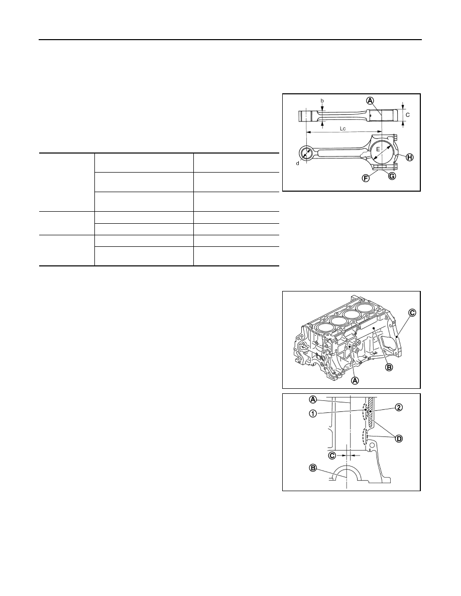
A
: Fracture-split surface
B
: Cylinder No
C
: Connecting rod big end diameter grade No
D
: Front mark
Connecting rod
Center dis-
tance
Lc [mm(in)]
139.02 (5.47)
Large end di-
ameter
× width
D
× B [mm(in)]
φ47 × 20.5 (0.27 × 0.81)
Small end di-
ameter
× width
d
× b [mm(in)]
φ22 × 20.5 (0.87 × 0.81)
Connecting rod
bearing
Inner diameter
[mm(in)]
φ44 (1.73)
Bearing width
[mm(in)]
16 (0.63)
Connecting rod
bolt
Thread size
M8
× 1.0
Length under
head
[mm(in)]
37.75 (1.49)
JSBIA2914ZZ
A
: Cylinder block
B
: Water piping
C
: Stamped location of engine model No.
1
: Mirror bore coating
2
: Water jacket
A
: Cylinder center
B
: Crankshaft center
C
: Offset
D
: Approximately the same temperature
JPBIA5024ZZ
JPBIA5025ZZ