Nissan Juke F15. Manual - part 652
EM-162
< SYSTEM DESCRIPTION >
[MR EXCEPT FOR NISMO RS MODELS]
COMPONENT PARTS
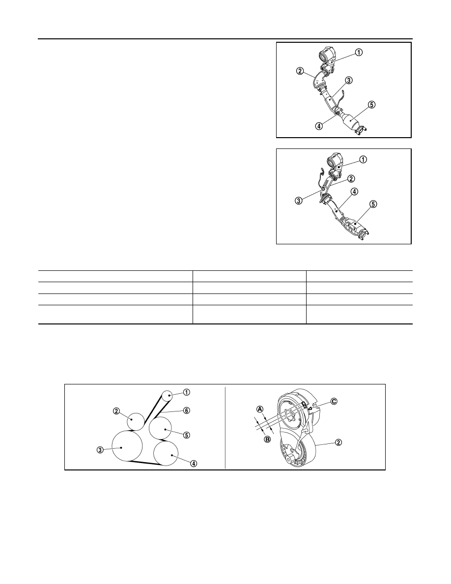
- 2WD
- AWD
SPECIFICATION
Drive Belt
INFOID:0000000012197346
• A serpentine belt
*
that drives all auxiliary devices with a single belt is used.
*
Serpentine
• The drive belt auto tensioner is installed between the crank pulley and alternator.
SPECIFICATION
• The belt used is a V-ribbed 6PK belt.
• The drive belt auto tensioner mechanism contains a coil spring and uses the idler pulley to maintain appro-
priate belt tension at all times, making regular belt tension adjustment unnecessary.
1
: Catalyst converter (supercharger
exit)
2
: Catalyst converter adapter
3
: Front tube
4
: Heated oxygen sensor 2
5
: Three-way catalyst converter (un-
der floor)
JSBIA5738ZZ
1
: Catalyst converter (supercharger
exit)
2
: Catalyst converter adapter
3
: Heated oxygen sensor 2
4
: Front tube
5
: Three-way catalyst converter (un-
der floor)
JSBIA5739ZZ
Installation position
Supercharger exit
Underfloor
Structure
Monolithic (ceramic)
Monolithic (ceramic)
Capacity
liters (US qt, Imp qt)
0.92 (1, 6/8)
1.20 (1-2/8, 1)
Catalyst precious metal
types
Palladium, rhodium
Palladium, rhodium
1.
Alternator
2.
Drive belt auto tensioner
3.
Crankshaft pulley
4.
A/C compressor
5.
Water pump
6.
Drive belt
A. Usable range
B. Range for installation of new drive
belt
C. Indicator
JSBIA5907ZZ