Nissan Juke F15. Manual - part 650


  Index      Nissan     Nissan Juke F15 (2015 year) - Service and Repair Manual


Search            


Content   ..  648  649  650  651   ..


Nissan Juke F15. Manual - part 650


EM-154

< PRECAUTION >

[MR EXCEPT FOR NISMO RS MODELS]

PRECAUTIONS

• Use torque wrench to tighten bolts or nuts to specification.

• When tightening nuts and bolts, as a basic rule, equally tighten in several different steps starting with the

ones in center, then ones on inside and outside diagonally in this order. If the order of tightening is specified,

do exactly as specified.

• Replace with new gasket, packing, oil seal or O-ring.

• Thoroughly wash, clean, and air-blow each part. Carefully check engine oil or engine coolant passages for

any restriction and blockage. 

• Avoid damaging sliding or mating surfaces. Completely remove foreign materials such as cloth lint or dust.

Before assembly, oil sliding surfaces well. 

• After disassembling, or exposing any internal engine parts, change engine oil and replace oil filter with a new

one.

• Release air within route when refilling after draining engine coolant. 

• After repairing, start the engine and increase engine speed to check engine coolant, fuel, engine oil, and

exhaust gases for leakage.

Parts Requiring Angle Tightening

INFOID:0000000012197333

• Use the angle wrench [SST:  KV10112100 (BT8653-A)] for the final tightening of the following engine parts: 

- Camshaft sprocket (INT) bolt

- Cylinder head bolts

- Main bearing cap bolts

- Connecting rod cap bolts

- Crankshaft pulley bolt (No the angle wrench is required as bolt flange is provided with notches for angle

tightening)

• Do not use a torque value for final tightening. 

• The torque value for these parts are for a preliminary step.

• Ensure thread and seat surfaces are clean and coated with engine oil. 

Liquid Gasket

INFOID:0000000012197334

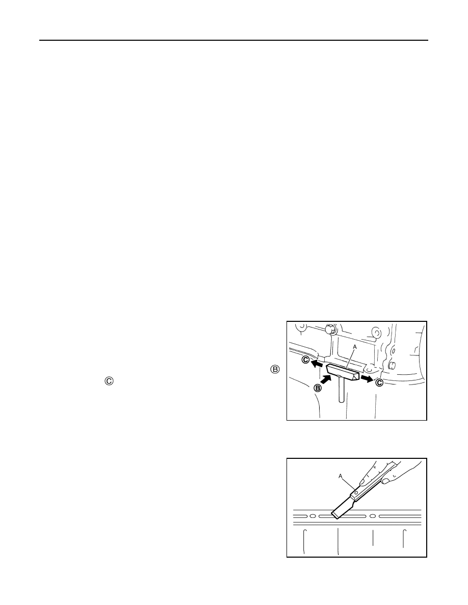
REMOVAL OF LIQUID GASKET SEALING

• After removing mounting nuts and bolts, separate the mating sur-

face using the seal cutter [SST:  KV10111100 (J-37228)] (A) and

remove old liquid gasket sealing.

CAUTION:

Never damage the mating surfaces.

• Tap the seal cutter [SST:  KV10111100 (J-37228)] to insert it  ,

and then slide it   by tapping on the side as shown in the figure.

• In areas where the seal cutter [SST:  KV10111100 (J-37228)] is dif-

ficult to use, lightly tap the parts using a plastic hammer to remove

it.

CAUTION:

If for some unavoidable reason tool such as a screwdriver is

used, never damage the mating surfaces.

LIQUID GASKET APPLICATION PROCEDURE

1. Using a scraper (A), remove old liquid gasket adhering to the liq-

uid gasket application surface and the mating surface.

• Remove liquid gasket completely from the groove of the liquid

gasket application surface, mounting bolts, and bolt holes.

2. Wipe the liquid gasket application surface and the mating sur-

face with white gasoline (lighting and heating use) to remove

adhering moisture, grease and foreign materials.

JPBIA0052ZZ

JPBIA0053ZZ

PRECAUTIONS

EM-155

< PRECAUTION >

[MR EXCEPT FOR NISMO RS MODELS]

C

D

E

F

G

H

I

J

K

L

M

A

EM

N

P

O

3. Attach liquid gasket tube to the tube presser (commercial ser-

vice tool).

Use Genuine Liquid Gasket or equivalent.

4. Apply liquid gasket without gaps to the specified location accord-

ing to the specified dimensions.

• If there is a groove for liquid gasket application, apply liquid

gasket to the groove.

• As for bolt holes  , normally apply liquid gasket inside the

holes. Occasionally, it should be applied outside the holes.

Check to read the text of this manual.

• Within five minutes of liquid gasket application, install the mat-

ing component.

• If liquid gasket protrudes, wipe it off immediately.

• Do not retighten mounting bolts or nuts after the installation.

• After 30 minutes or more have passed from the installation, fill

engine oil and engine coolant.

CAUTION:

If there are specific instructions in this manual, observe them.

EMA0622D

: Groove

: Inside

JPBIA0010ZZ

EM-156

< PREPARATION >

[MR EXCEPT FOR NISMO RS MODELS]

PREPARATION

PREPARATION

PREPARATION

Special Service Tools

INFOID:0000000012197335

Tool number
(TechMate No.)
Tool name

Description

KV10111100
(J-37228)
Seal cutter

Removing parts with liquid gasket ap-
plied

KV10114400
(J-38365)
Heated oxygen sensor wrench

Loosening or tightening heated oxy-
gen sensor 2 (AWD models)
a: For 22 mm (0.87 in) width hexa-
gon nut

KV10113700
or
KV10117100
(J-3647-A)
Heated oxygen sensor socket

Loosening or tightening air fuel ratio 
sensor 1
For 22 mm (0.87 in) width hexagon 
nut

KV11103000
(  —  )
Pulley puller

Removing crankshaft pulley

KV10112100
(BT8653-A)
Angle wrench

Checking tightening angle

KV10116200
(J-26336-A)
Valve spring compressor
1. KV10115900
(J-26336-20)
Attachment
2. KV10109220
(  —  )
Adapter

Disassembling and assembling valve 
mechanism
Part (1) is a component of 
KV10116200 (J-26336-A), but Part (2) 
is not so.

ZZA0013D

S-NT636

ZZA1007D

ZZA0010D

ZZA0120D

PBIC1650E

PREPARATION

EM-157

< PREPARATION >

[MR EXCEPT FOR NISMO RS MODELS]

C

D

E

F

G

H

I

J

K

L

M

A

EM

N

P

O

KV10107902
(J-38959)
Valve oil seal puller

Removing valve oil seal

KV10115600
(J-38958)
Valve oil seal drift

Installing valve oil seal
Use side A (G).
a: 20 (0.79) dia.             d: 8 (0.31) dia.
b: 13 (0.51) dia.             e: 10.7 (0.421)
c: 10.3 (0.406) dia.         f: 5 (0.20)
H: Side B
                                                   Unit: mm (in)

KV11105210
(J-44716)
Stopper plate

Removing and installing crankshaft 
pulley

ST16610001
(J-23907)
Pilot bushing puller

Removing pilot converter

KV10119600
(  —  )
Injector remover

Removing and installing fuel injector

KV101197S0
(  —  )
Injector seal drift set

Installing fuel injector seal

Tool number
(TechMate No.)
Tool name

Description

ZZA0015D

JPBIA0396ZZ

ZZA0009D

ZZA0046D

JPBIA3746ZZ

JPBIA3281ZZ


Content   ..  648  649  650  651   ..