Nissan Juke F15. Manual - part 640
EM-114
< UNIT DISASSEMBLY AND ASSEMBLY >
[MR FOR NISMO RS MODELS]
CYLINDER BLOCK
CYLINDER BLOCK
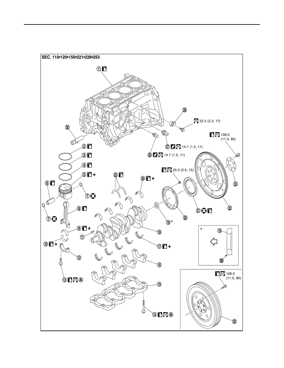
Exploded View
INFOID:0000000012197309
1.
Cylinder block
2.
Top ring
3.
Second ring
4.
Oil ring
5.
Piston
6.
Piston pin
7.
Snap ring
8.
Connecting rod
9.
Connecting rod bearing (upper)
JPBIA5495GB