Nissan Juke F15. Manual - part 589
P2562, P2566 WASTEGATE CONTROL VALVE POSITION SENSOR
EC-1169
< DTC/CIRCUIT DIAGNOSIS >
[MR EXCEPT FOR NISMO RS MODELS]
C
D
E
F
G
H
I
J
K
L
M
A
EC
N
P
O
NO
>> Perform the trouble diagnosis for power supply circuit.
2.
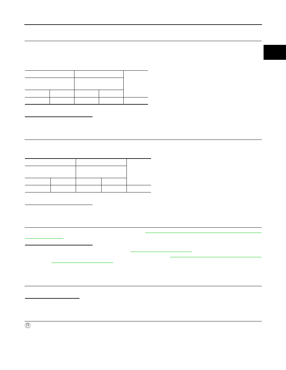
CHECK WASTEGATE CONTROL VALVE POSITION SENSOR GROUND CIRCUIT
1. Turn ignition switch OFF.
2. Disconnect ECM harness connector.
3. Check the continuity between electric wastegate control actuator harness connector and ECM harness
connector.
4. Also check harness for short to power.
Is the inspection result normal?
YES
>> GO TO 3.
NO
>> Repair or replace error-detected parts.
3.
CHECK WASTEGATE CONTROL VALVE POSITION SENSOR INPUT SIGNAL CIRCUIT
1. Check the continuity between electric wastegate control actuator harness connector and ECM harness
connector.
2. Also check harness for short to ground and to power.
Is the inspection result normal?
YES
>> GO TO 4.
NO
>> Repair or replace error-detected parts.
4.
CHECK ELECTRIC WASTEGATE CONTROL ACTUATOR
Check the electric wastegate control actuator. Refer to
EC-1169, "Component Inspection (Electric Wastegate
.
Is the inspection result normal?
YES
>> Check intermittent incident. Refer to
GI-45, "Intermittent Incident"
.
NO
>> Replace electric wastegate control actuator. Refer to
EC-600, "ENGINE CONTROL SYSTEM :
.
Component Inspection (Electric Wastegate Control Actuator)
INFOID:0000000012198695
1.
INSPECTION START
Do you have CONSULT?
Do you have CONSULT?
YES
>> GO TO 2.
NO
>> GO TO 3.
2.
CHECK ELECTRIC WASTEGATE CONTROL ACTUATOR
With CONSULT
1. Turn ignition switch ON and engine stopped.
2. On the CONSULT screen, select “ENGINE” >> “ACTIVE TEST” >> “WASTEGATE ACTUATOR”.
3. Operate “Up” or “Down”, set “W/G ACTUATOR POSITION B1” to 0.002 m, and make a quick short note of
value “V1” of “W/G ACTUATOR POSI SEN B1”.
+
−
Continuity
Electric wastegate control
actuator
ECM
Connector
Terminal
Connector
Terminal
F61
2
F24
72
Existed
+
−
Continuity
Electric wastegate control
actuator
ECM
Connector
Terminal
Connector
Terminal
F61
1
F24
65
Existed