Nissan Juke F15. Manual - part 587


  Index      Nissan     Nissan Juke F15 (2015 year) - Service and Repair Manual


Search            


Content   ..  585  586  587  588   ..


Nissan Juke F15. Manual - part 587


P219A AIR FUEL RATIO

EC-1161

< DTC/CIRCUIT DIAGNOSIS >

[MR EXCEPT FOR NISMO RS MODELS]

C

D

E

F

G

H

I

J

K

L

M

A

EC

N

P

O

6.

CHECK FUNCTION OF IGNITION COIL-1

CAUTION:

Perform the following steps in a well-ventilated area with no combustibles.

1. Turn ignition switch OFF.

2. Remove fuel pump fuse from IPDM E/R to release fuel pressure.

NOTE:

CONSULT must not be used to release fuel pressure. It develops again during the following steps,

if released by using CONSULT.

3. Start the engine.

4. After an engine stall, crank the engine two or three times to release all the fuel pressure. 

5. Turn ignition switch OFF.

6. Disconnect all the harness connectors of ignition coil to prevent electric discharge from occurring in igni-

tion coil.

7. Remove ignition coil assembly and spark plug of cylinder. Refer to 

EM-214, "Removal and Installation"

.

8. Crank engine for 5 seconds or more to remove combustion gas in the cylinder.

9. Connect spark plug and harness connector to ignition coil.

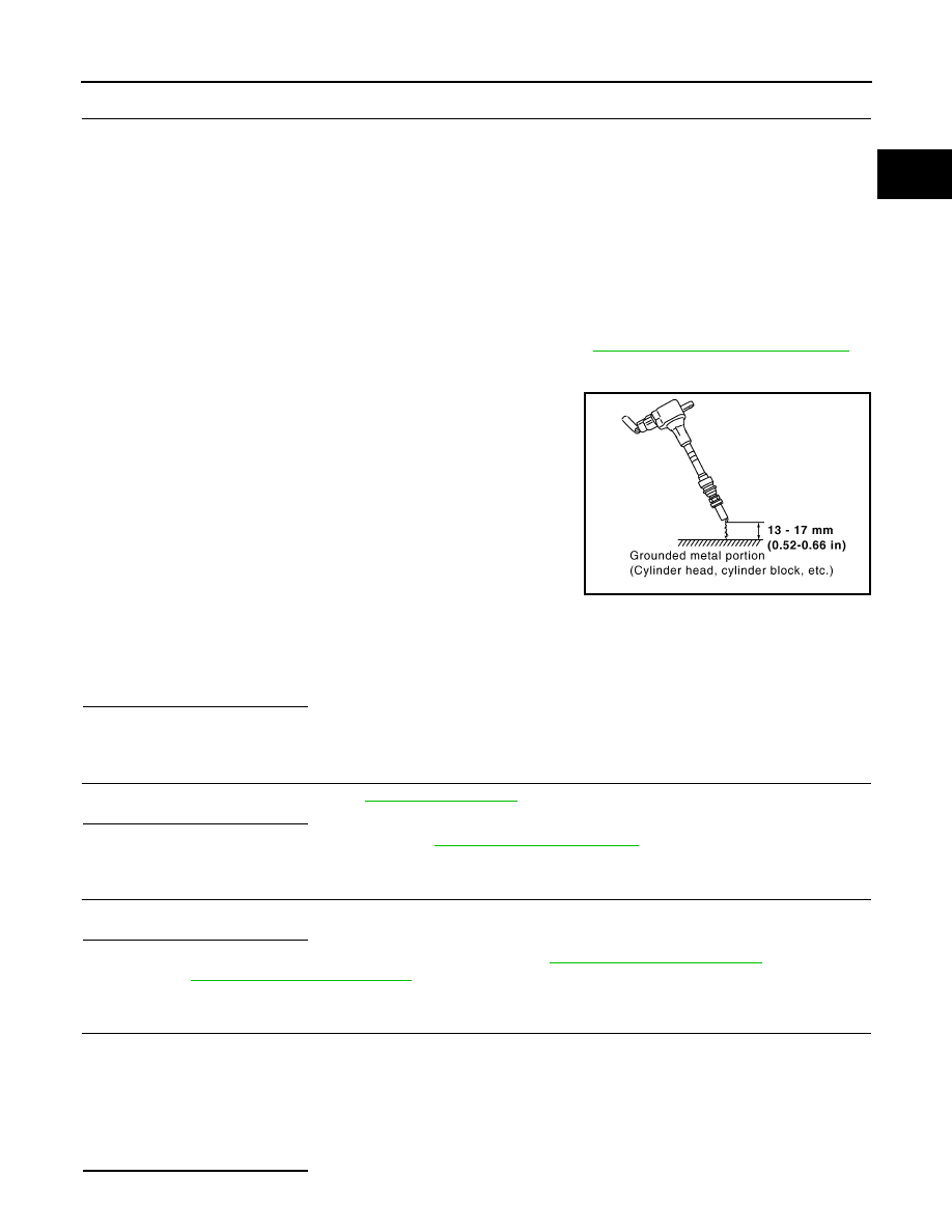
10. Allow a 13-17mm (0.52-0.66 in) spacing between spark plug and

grounded metal portion as shown in the figure to fix the ignition

coil with a rope or an equivalent.

11. Crank the engine for approximately 3 seconds to see if sparking

occurs between spark plug and the grounded metal portion.

CAUTION:

• The discharge voltage becomes 20 kV or higher. There-

fore, always stay away from the spark plug and ignition

coil at least 50 cm (19.7 in) during the inspection.

• Leaving a space of more than 17mm (0.66 in) may damage

the ignition coil.

NOTE:

When the gap is less than 13 mm (0.52 in), a the spark might be generated even if the coil is mal-

functioning.

Is the inspection result normal?

YES

>> GO TO 7.

NO

>> GO TO 9.

7.

CHECK COMPRESSION PRESSURE

Check compression pressure. Refer to 

EM-182, "Inspection"

.

Is the inspection result normal?

YES

>> Check intermittent incident. Refer to 

GI-45, "Intermittent Incident"

.

NO

>> Check pistons, piston rings, valves, valve seats and cylinder head gaskets.

8.

DETECT MALFUNCTIONING PART

Check fuel hoses and fuel tubes for clogging.
Is the inspection result normal?

YES

>> Replace fuel filter and fuel pump assembly. Refer to 

FL-6, "2WD : Exploded View"

 (2WD models)

or 

FL-10, "AWD : Exploded View"

 (AWD models).

NO

>> Repair or replace error-detected parts.

9.

CHECK FUNCTION OF IGNITION COIL-2

1. Turn ignition switch OFF.

2. Disconnect spark plug and connect a non-malfunctioning spark plug.

3. Crank engine for approximately 3 seconds, and recheck whether spark is generated between the spark

plug and the grounded metal portion.

Is the inspection result normal?

Spark should be generated.

JMBIA0066GB

Spark should be generated.

EC-1162

< DTC/CIRCUIT DIAGNOSIS >

[MR EXCEPT FOR NISMO RS MODELS]

P219A AIR FUEL RATIO

YES

>> GO TO 10.

NO

>> Check ignition coil, power transistor and their circuits. Refer to 

EC-1229, "Component Function

Check"

.

10.

CHECK SPARK PLUG

Check the initial spark plug for fouling, etc.
Is the inspection result normal?

YES

>> 1. Repair or clean spark plug. Refer to 

EM-214,

"Exploded View"

.

2. GO TO 11.

NO

>> Replace spark plug(s) with standard type one(s). For

spark plug type, refer to 

EM-312, "Spark Plug"

.

11.

CHECK FUNCTION OF IGNITION COIL-3

1. Reconnect the initial spark plugs.

2. Crank engine for approximately 3 seconds, and recheck whether spark is generated between the spark

plug and the grounded portion.

Is the inspection result normal?

YES

>> Check intermittent incident. Refer to 

GI-45, "Intermittent Incident"

.

NO

>> Replace spark plug(s) with standard type one(s). For spark plug type, refer to 

EM-312, "Spark

Plug"

.

SEF156I

Spark should be generated.

P2263 TC SYSTEM

EC-1163

< DTC/CIRCUIT DIAGNOSIS >

[MR EXCEPT FOR NISMO RS MODELS]

C

D

E

F

G

H

I

J

K

L

M

A

EC

N

P

O

P2263 TC SYSTEM

DTC Logic

INFOID:0000000012198684

DTC DETECTION LOGIC

NOTE:

If DTC P2263 is displayed with DTC P0237 or P0238, first perform the trouble diagnosis for DTC P0237 or

P0238. Refer to 

EC-938, "DTC Logic"

.

DTC CONFIRMATION PROCEDURE

1.

PERFORM COMPONENT FUNCTION CHECK

Perform component function check. Refer to 

EC-1163, "Component Function Check"

.

NOTE:

Use component function check to check the overall function of the turbocharger system circuit. During this

check, a 1st trip DTC might not be confirmed.
Is the inspection result normal?

YES

>> INSPECTION END

NO

>> Proceed to 

EC-1164, "Diagnosis Procedure"

.

Component Function Check

INFOID:0000000012198685

1.

INSPECTION START

Do you have CONSULT?

YES

>> GO TO 2.

NO

>> GO TO 3.

2.

CHECK ELECTRIC WASTEGATE CONTROL ACTUATOR

With CONSULT

1. Turn ignition switch ON and engine stopped.

2. On the CONSULT screen, select “ENGINE” >> “ACTIVE TEST” >> “WASTEGATE ACTUATOR”.

3. Operate “Up” or “Down”, set “W/G ACTUATOR POSITION B1” to 0.002 m, and make a quick short note of

value “V1” of “W/G ACTUATOR POSI SEN B1”.

4. Operate “Up” or “Down”, set “W/G ACTUATOR POSITION B1” to 0.006 m, and make a quick short note of

value “V2” of “W/G ACTUATOR POSI SEN B1”.

Do the values of “V1” and “V2” change (visually, ACTUATOR SHAFT operates) and “V2” minus “V1” becomes

equal to or more than 1.3V?

YES

>> INSPECTION END

NO

>> Refer to 

EC-1164, "Diagnosis Procedure"

.

3.

CHECK ELECTRIC WASTEGATE CONTROL ACTUATOR

DTC No.

Trouble diagnosis name

(Trouble diagnosis content)

DTC detecting condition

Possible cause

P2263

TC SYSTEM-B1
(Turbocharger boost system 
performance)

In spite of the boosting area, the boost does 
not increase.

• Intake air leaks
• Exhaust gas leaks
• Turbocharger boost sensor
• Turbocharger boost control solenoid 

valve

• Exhaust manifold and turbocharger 

assembly

• Electric wastegate control actuator
• Harness or connectors

(Electric wastegate control actuator 
circuit is open or shorted.)

• Turbocharger bypass control valve
• Harness or connectors

(Turbocharger bypass control valve 
circuit is open or shorted.)

EC-1164

< DTC/CIRCUIT DIAGNOSIS >

[MR EXCEPT FOR NISMO RS MODELS]

P2263 TC SYSTEM

Without CONSULT

1. Turn ignition switch OFF.

2. Disconnect Wastegate control actuator harness connector.

3. While checking the POSITION SENSOR OUT voltage with an oscilloscope, apply a voltage of 12 V to the

positive or negative terminal.

Does ACTUATOR SHAFT visually operate and POSITION SENSOR OUT voltage change?

YES

>> INSPECTION END

NO

>> Refer to 

EC-1164, "Diagnosis Procedure"

.

Diagnosis Procedure

INFOID:0000000012198686

1.

CHECK FOR EXHAUST GAS LEAK

1. Start engine and run it at idle.

2. Listen for an exhaust gas leak of exhaust manifold.
Is exhaust gas leak detected?

YES

>> Repair or replace malfunction parts.

NO

>> GO TO 2.

2.

CHECK FOR INTAKE AIR LEAK

Listen for an intake air leak between electric throttle control actuator and compressor wheel.
Is intake air leak detected?

YES

>> Repair or replace malfunction parts.

NO

>> GO TO 3.

3.

CHECK RECIRCULATION VALVE

1. Turn ignition switch OFF.

2. Check recirculation valve. Refer to 

EM-244, "Inspection"

.

Is the inspection result normal?

YES

>> GO TO 4.

NO

>> Replace recirculation valve. Refer to 

EM-242, "Exploded View"

.

4.

CHECK TURBOCHARGER BYPASS CONTROL VALVE POWER SUPPLY

1. Disconnect turbocharger bypass control valve harness connector.

2. Turn ignition switch ON.

3. Check the voltage between turbocharger bypass control valve harness connector and ground.

Is the inspection result normal?

YES

>> GO TO 6.

NO

>> GO TO 5.

5.

CHECK TURBOCHARGER BYPASS CONTROL VALVE POWER SUPPLY CIRCUIT

1. Turn ignition switch OFF.

2. Disconnect IPDM E/R harness connector.

3. Check the continuity between turbocharger bypass control valve harness connector and IPDM E/R har-

ness connector.

+

Voltage

Turbocharger bypass control valve

Connector

Terminal

F64

1

Ground

Battery voltage

+

Continuity

Turbocharger bypass control 

valve

IPDM E/R

Connector

Terminal

Connector

Terminal

F64

1

E14

36

Existed


Content   ..  585  586  587  588   ..