Nissan Juke F15. Manual - part 566
P119C FUEL RAIL PRESSURE SENSOR
EC-1077
< DTC/CIRCUIT DIAGNOSIS >
[MR EXCEPT FOR NISMO RS MODELS]
C
D
E
F
G
H
I
J
K
L
M
A
EC
N
P
O
P119C FUEL RAIL PRESSURE SENSOR
DTC Logic
INFOID:0000000012198594
DTC DETECTION LOGIC
DTC CONFIRMATION PROCEDURE
1.
CHECK DTC PRIORITY
If DTC P119C is displayed with DTC P0190, first perform the confirmation procedure (trouble diagnosis) for
DTC P0190.
Is applicable DTC detected?
YES
>> Perform diagnosis of applicable. Refer to
.
NO
>> GO TO 2.
2.
PRECONDITIONING-1
If DTC Confirmation Procedure is previously conducted, always perform the following procedure before con-
ducting the next test.
1. Turn ignition switch OFF and wait at least 10 seconds.
2. Turn ignition switch ON.
3. Turn ignition switch OFF and wait at least 10 seconds.
TESTING CONDITION:
• Before performing the following procedure, check that battery voltage is 9 V or more with ignition
switch ON.
• Remaining fuel amount must be 15% or more.
>> GO TO 3.
3.
PERFORM DTC CONFIRMATION PROCEDURE
1. Start the engine and warm it up until the engine coolant temperature reaches 70
°C (158°F) or more.
2. Drive the vehicle and accelerate 3 consecutive seconds or more with the engine speed 1,500 rpm or
more.
3. Check “Self-diagnostic result” of “ENGINE”.
Is the DTC detected?
YES
>> Proceed to
EC-1077, "Diagnosis Procedure"
.
NO-1 >> To check malfunction symptom before repair: Refer to
GI-45, "Intermittent Incident"
NO-2 >> Confirmation after repair: INSPECTION END
Diagnosis Procedure
INFOID:0000000012198595
NOTE:
Turning the ignition switch ON with FRP sensor harness connector disconnected causes ECM to
detect DTC P119C. Be sure to erase the DTC when the diagnosis procedure.
1.
CHECK DTC PRIORITY
If DTC P119C is displayed with DTC P0190, first perform the confirmation procedure (trouble diagnosis) for
DTC P0190.
Is applicable DTC detected?
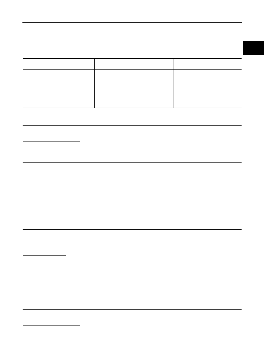
DTC No.
CONSULT screen terms
(Trouble diagnosis content)
DTC detecting condition
Possible cause
P119C
FUEL PRESSURE SENSOR
(Fuel pressure sensor)
All of the following conditions are satisfied:
• Battery voltage: 8 V or more
• Engine speed: 50 rpm or more
• Engine coolant temperature: With a back-
ground of 65
°C (149°F) or more during the
trip
• Remaining fuel amount: 15% or more
• Fuel cut: No
• Harness or connectors
(Fuel rail pressure sensor circuit is
open or shorted.)
• Fuel rail pressure sensor
• Sensor power supply 2