Nissan Juke F15. Manual - part 530
P0234 TC SYSTEM
EC-933
< DTC/CIRCUIT DIAGNOSIS >
[MR EXCEPT FOR NISMO RS MODELS]
C
D
E
F
G
H
I
J
K
L
M
A
EC
N
P
O
NO
>> Replace Turbocharger Assembly (do not replace electric wastegate control actuator only). Refer
to
EC-600, "ENGINE CONTROL SYSTEM : Component Parts Location"
Diagnosis Procedure
INFOID:0000000012198432
1.
CHECK BOOST CONTROL ACTUATOR HOSE
Check disconnection, looseness or improper connection of hose between turbocharger bypass control valve
solenoid valve and boost control actuator.
Is the inspection result normal?
YES
>> GO TO 2.
NO
>> Repair or replace error-detected parts.
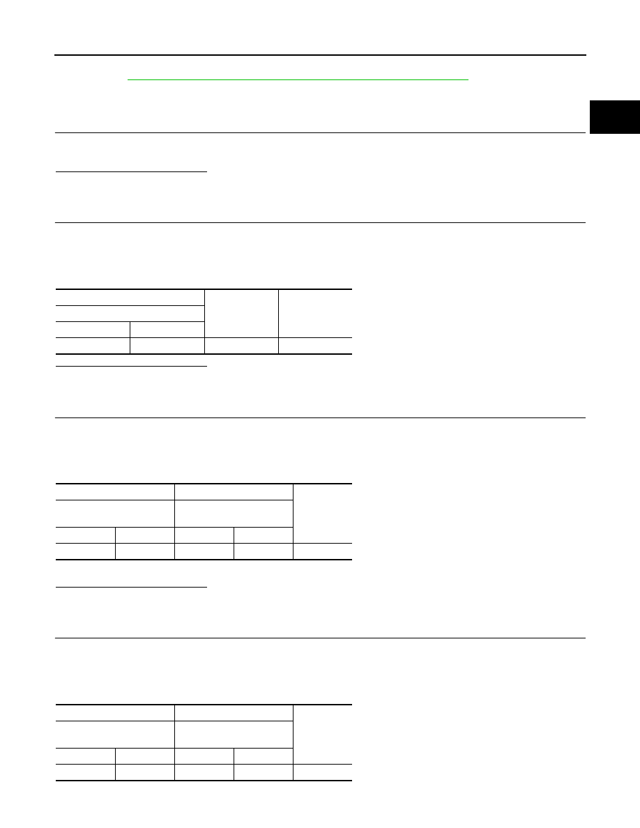
2.
CHECK TURBOCHARGER BYPASS CONTROL VALVE POWER SUPPLY
1. Turn ignition switch OFF.
2. Disconnect turbocharger bypass control valve harness connector.
3. Turn ignition switch ON.
4. Check the voltage between turbocharger bypass control valve harness connector and ground.
Is the inspection result normal?
YES
>> GO TO 4.
NO
>> GO TO 3.
3.
CHECK TURBOCHARGER BYPASS CONTROL VALVE POWER SUPPLY CIRCUIT
1. Turn ignition switch OFF.
2. Disconnect IPDM E/R harness connector.
3. Check the continuity between turbocharger bypass control valve harness connector and IPDM E/R har-
ness connector.
4. Also check harness for short to ground and short.
Is the inspection result normal?
YES
>> Perform the trouble diagnosis for power supply circuit.
NO
>> Repair or replace error-detected parts.
4.
CHECK TURBOCHARGER BYPASS CONTROL VALVE GROUND CIRCUIT
1. Turn ignition switch OFF.
2. Disconnect ECM harness connector.
3. Check the continuity between turbocharger bypass control valve harness connector and ECM harness
connector.
4. Also check harness for short to power.
+
−
Voltage
Turbocharger bypass control valve
Connector
Terminal
F64
1
Ground
Battery voltage
+
−
Continuity
Turbocharger bypass con-
trol valve
IPDM E/R
Connector
Terminal
Connector
Terminal
F64
1
E14
36
Existed
+
−
Continuity
Turbocharger bypass con-
trol valve
ECM
Connector
Terminal
Connector
Terminal
F64
2
F24
105
Existed