Nissan Juke F15. Manual - part 509


  Index      Nissan     Nissan Juke F15 (2015 year) - Service and Repair Manual


Search            


Content   ..  507  508  509  510   ..


Nissan Juke F15. Manual - part 509


P0106 TC BOOST SENSOR

EC-849

< DTC/CIRCUIT DIAGNOSIS >

[MR EXCEPT FOR NISMO RS MODELS]

C

D

E

F

G

H

I

J

K

L

M

A

EC

N

P

O

2. Check the power supply of the turbocharger boost sensor.

Is the inspection result normal?

YES

>> GO TO 6.

NO

>> Perform trouble diagnosis for power supply circuit.

6.

CHECK TURBOCHARGER BOOST SENSOR CIRCUIT FOR OPEN AND SHORT

Check turbocharger boost sensor circuit for open and short.

Is the inspection result normal?

YES

>> Check intermittent incident. Refer to 

GI-45, "Intermittent Incident"

.

NO

>> Repair or replace error-detected parts.

Component Inspection

INFOID:0000000012198352

1.

CHECK TURBOCHARGER BOOST SENSOR 

1. Turn ignition switch OFF.

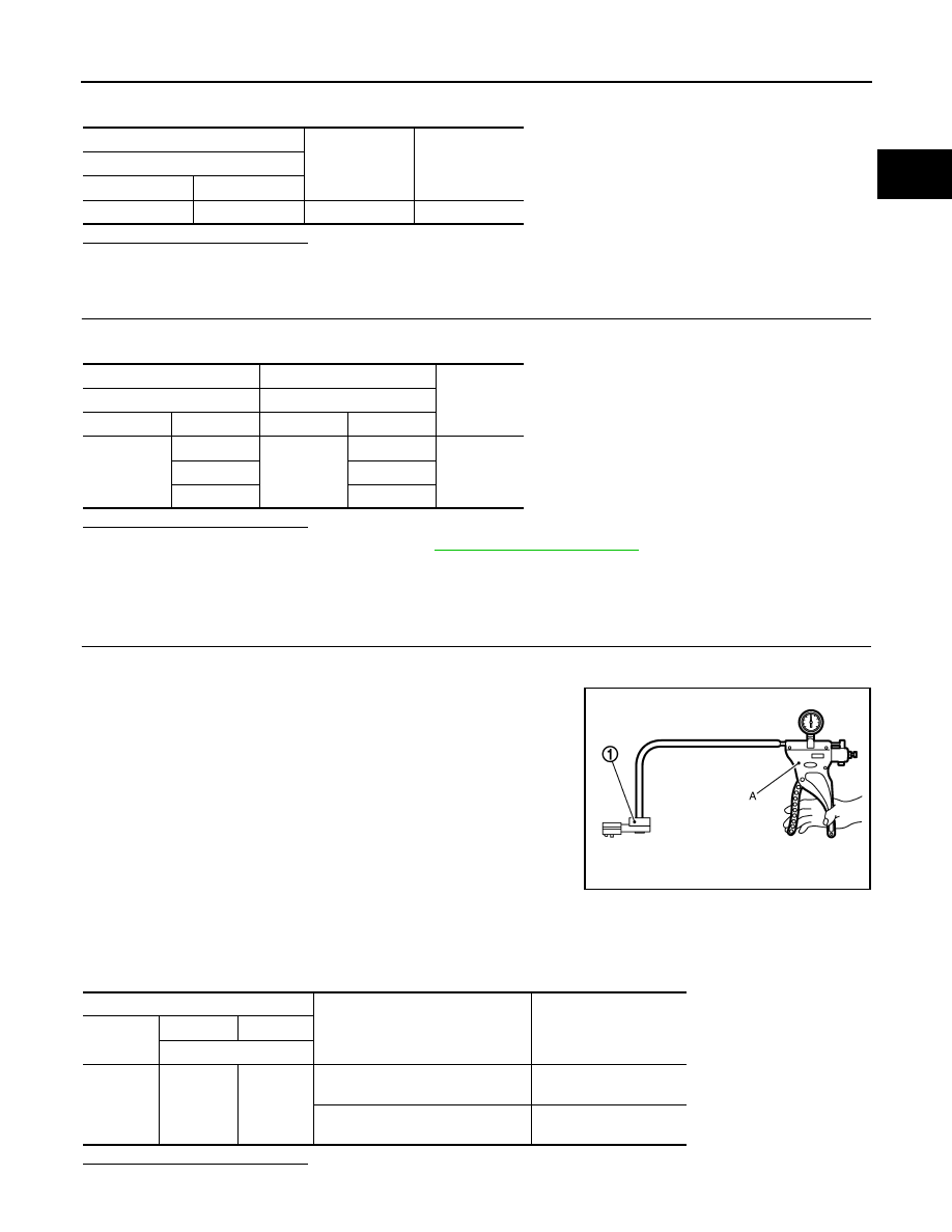
2. Remove turbocharger boost sensor with its harness connector.

3. Install pressure pump (A) to turbocharger boost sensor (1).

CAUTION:

When insert a pressure pump hose to the sensor, be careful

to the damage of the sensor housing.

4. Turn ignition switch ON.

5. Check the voltage between ECM harness connector terminals

as per the following conditions.

NOTE:

• Always calibrate the pressure pump gauge when using it.

• Inspection should be done at room temperature [10 - 30

°C (50 - 86°F)].

Is the inspection result normal?

YES

>> INSPECTION END

+

-

Voltage

(Approx.)

Turbocharger boost sensor

Connector

Terminal

F75

2

Ground

5.0 V

+

-

Continuity

ECM

Turbocharger boost sensor

Connector

Terminal

Connector

Terminal

F23

11

F75

1

Existed

13

4

29

2

JMBIA0871ZZ

ECM

Condition [Pressure (Relative to at-

mospheric pressure)]

Voltage

(Approx.)

Connector

+

Terminal

F23

11

13

0 kPa
(0 mbar, 0 mmHg, 0 inHg)

2.03 V

40 kPa
(400 mbar, 300 mmHg, 11.81 inHg)

2.67 V

EC-850

< DTC/CIRCUIT DIAGNOSIS >

[MR EXCEPT FOR NISMO RS MODELS]

P0106 TC BOOST SENSOR

NO

>> Replace turbocharger boost sensor. Refer to 

EM-194, "Exploded View"

.

P010A MANIFOLD ABSOLUTE PRESSURE SENSOR

EC-851

< DTC/CIRCUIT DIAGNOSIS >

[MR EXCEPT FOR NISMO RS MODELS]

C

D

E

F

G

H

I

J

K

L

M

A

EC

N

P

O

P010A MANIFOLD ABSOLUTE PRESSURE SENSOR

DTC Logic

INFOID:0000000012198353

DTC DETECTION LOGIC

NOTE:

If DTC P010A is displayed with DTC P0643, first perform the trouble diagnosis for DTC P0643. 

Refer to 

EC-1060, "DTC Logic"

.

DTC CONFIRMATION PROCEDURE

1.

PRECONDITIONING 

If DTC Confirmation Procedure has been previously conducted, always perform the following procedure

before conducting the next test. 

1. Turn ignition switch OFF and wait at least 10 seconds.

2. Turn ignition switch ON.

3. Turn ignition switch OFF and wait at least 10 seconds.

>> GO TO 2.

2.

PERFORM DTC CONFIRMATION PROCEDURE

1. Start engine and let it idle for 10 seconds.

2. Check DTC.
Is DTC detected?

YES

>> Proceed to 

EC-851, "Diagnosis Procedure"

.

NO

>> INSPECTION END

Diagnosis Procedure

INFOID:0000000012198354

1.

CHECK GROUND CONNECTION

1. Turn ignition switch OFF.

2. Check ground connection M95. Refer to Ground Inspection in 

GI-48, "Circuit Inspection"

.

Is the inspection result normal?

YES

>> GO TO 2.

NO

>> Repair or replace ground connection.

2.

CHECK MAP SENSOR POWER SUPPLY CIRCUIT

1. Disconnect MAP sensor harness connector.

2. Turn ignition switch ON.

3. Check the voltage between manifold absolute pressure sensor (MAP) sensor harness connector and

ground.

Is the inspection result normal?

YES

>> GO TO 3.

NO

>> Repair open circuit or short to ground or short to power in harness or connectors.

3.

CHECK MAP SENSOR GROUND CIRCUIT FOR OPEN AND SHORT

DTC No.

Trouble diagnosis name

DTC detecting condition

Possible cause

P010A

Manifold absolute pressure sensor 
circuit

• An excessively low voltage from 

the sensor is sent to ECM.

• An excessively high voltage from 

the sensor is sent to ECM.

• Harness or connectors

(The sensor circuit is open or 
shorted.)

• Manifold absolute pressure (MAP) 

sensor

MAP sensor

Ground

Voltage (V)

Connector

Terminal

F76

1

Ground

Approx. 5

EC-852

< DTC/CIRCUIT DIAGNOSIS >

[MR EXCEPT FOR NISMO RS MODELS]

P010A MANIFOLD ABSOLUTE PRESSURE SENSOR

1. Turn ignition switch OFF.

2. Disconnect ECM harness connector.

3. Check the continuity between MAP sensor harness connector and ECM harness connector.

4. Also check harness for short to ground and power.
Is the inspection result normal?

YES

>> GO TO 4.

NO

>> Repair open circuit, short to ground or short to power in harness or connectors.

4.

CHECK MAP SENSOR INPUT SIGNAL CIRCUIT FOR OPEN AND SHORT

1. Check the continuity between MAP sensor harness connector and ECM harness connector.

2. Also check harness for short to ground and power.
Is the inspection result normal?

YES

>> GO TO 5.

NO

>> Repair open circuit, short to ground or short to power in harness or connectors.

5.

CHECK MAP SENSOR

Refer to 

EC-852, "Component Inspection"

.

Is the inspection result normal?

YES

>> GO TO 6.

NO

>> Replace MAP sensor.

6.

CHECK INTERMITTENT INCIDENT

Refer to 

GI-45, "Intermittent Incident"

.

>> INSPECTION END

Component Inspection

INFOID:0000000012198355

1.

CHECK MAP SENSOR-I

1. Turn ignition switch OFF.

2. Start engine and warm it up to normal operating temperature.

3. Turn ignition switch OFF, wait at least 5 seconds and then turn ON.

4. Check the voltage between ECM harness connector terminals as follows.

NOTE:

• To avoid the influence of intake manifold vacuum, check the voltage 1 or more minutes past after engine

is stopped.

• Because the sensor is absolute pressure sensor, output value may differ depending on atmospheric

pressure and altitude.

5. Measure the atmospheric pressure.

NOTE:

MAP sensor

ECM

Continuity

Connector

Terminal

Connector

Terminal

F76

3

F23

43

Existed

MAP sensor

ECM

Continuity

Connector

Terminal

Connector

Terminal

F76

2

F23

31

Existed

ECM

Connector

+

Terminal

F23

31

43


Content   ..  507  508  509  510   ..