Nissan Juke F15. Manual - part 435


  Index      Nissan     Nissan Juke F15 (2015 year) - Service and Repair Manual


Search            


Content   ..  433  434  435  436   ..


Nissan Juke F15. Manual - part 435


HIGH PRESSURE FUEL PUMP

EC-553

< DTC/CIRCUIT DIAGNOSIS >

[MR FOR NISMO RS MODELS]

C

D

E

F

G

H

I

J

K

L

M

A

EC

N

P

O

NO

>> Replace high pressure fuel pump. Refer to 

EM-49, "Exploded View"

.

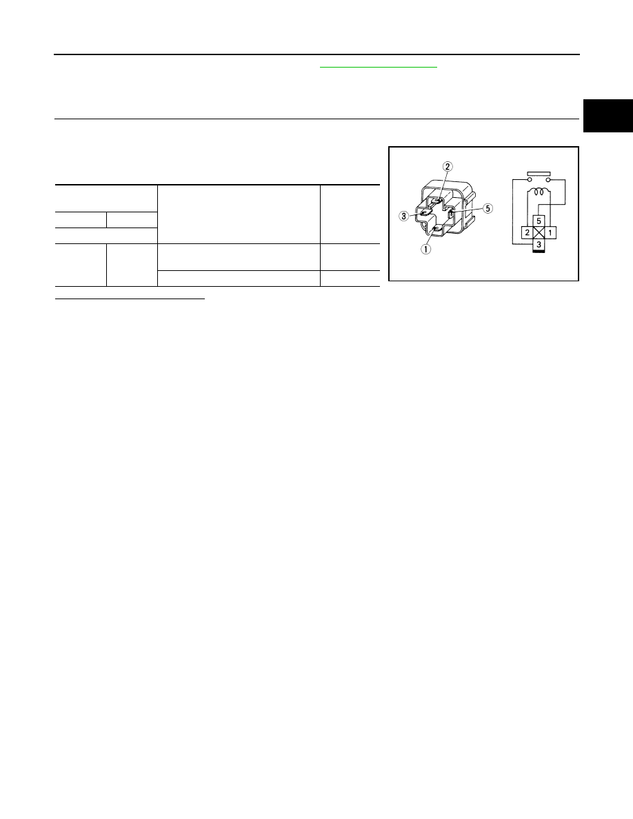
Component Inspection (High Pressure Fuel Pump Relay)

INFOID:0000000012198097

1.

CHECK HIGH PRESSURE FUEL PUMP RELAY

1. Turn ignition switch OFF.

2. Remove high pressure fuel pump relay.

3. Check the continuity between high pressure fuel pump relay ter-

minals as per the following conditions.

Is the inspection result normal?

YES

>> INSPECTION END

NO

>> Replace high pressure fuel pump relay.

High pressure fuel 

pump relay

Conditions

Continuity

+

Terminal

3

5

12 V direct current supply between ter-
minals 1 and 2

Existed

No current supply

Not existed

SEF090M

EC-554

< DTC/CIRCUIT DIAGNOSIS >

[MR FOR NISMO RS MODELS]

IGNITION SIGNAL

IGNITION SIGNAL

Component Function Check

INFOID:0000000012198098

1.

INSPECTION START

Turn ignition switch OFF, and restart engine.
Does the engine start?

YES

>> GO TO 2.

NO

>> Proceed to 

EC-554, "Diagnosis Procedure"

.

2.

IGNITION SIGNAL FUNCTION

With CONSULT

1. Perform “POWER BALANCE” in “ACTIVE TEST” mode of “ENGINE” using CONSULT.

2. Check that each circuit produces a momentary engine speed drop.

Without CONSULT

1. Let engine idle.

2. Check the voltage signal between ECM harness connector and ground with an oscilloscope.

NOTE:

The pulse cycle changes depending on rpm at idle.

Is the inspection result normal?

YES

>> INSPECTION END

NO

>> Proceed to 

EC-554, "Diagnosis Procedure"

.

Diagnosis Procedure

INFOID:0000000012198099

1.

CHECK CONDENSER POWER SUPPLY

1. Turn ignition switch OFF.

2. Disconnect condenser harness connector.

3. Turn ignition switch ON.

4. Check the voltage between condenser harness connector and ground.

Is the inspection result normal?

YES

>> GO TO 3.

NO

>> GO TO 2.

2.

CHECK CONDENSER POWER SUPPLY CIRCUIT

1. Turn ignition switch OFF.

2. Disconnect IPDM E/R harness connector.

3. Check the continuity between IPDM E/R harness connector and condenser harness connector.

ECM

Voltage signal

+

Connector

Terminal

Connector

Terminal

F26

82

E18

127

86

90

94

JPBIA4733ZZ

+

Voltage

Condenser

Connector

Terminal

F13

1

Ground

Battery voltage

IGNITION SIGNAL

EC-555

< DTC/CIRCUIT DIAGNOSIS >

[MR FOR NISMO RS MODELS]

C

D

E

F

G

H

I

J

K

L

M

A

EC

N

P

O

4. Also check harness for short to ground.
Is the inspection result normal?

YES

>> Perform the trouble diagnosis for power supply circuit.

NO

>> Repair or replace error-detected parts.

3.

CHECK CONDENSER GROUND CIRCUIT

1. Turn ignition switch OFF.

2. Check the continuity between Condenser harness connector and ground.

3. Also check harness for short to power.
Is the inspection result normal?

YES

>> GO TO 4.

NO

>> Repair or replace error-detected parts.

4.

CHECK CONDENSER

Check the condenser. refer to 

EC-557, "Component Inspection (Condenser)"

.

Is the inspection result normal?

YES

>> GO TO 5.

NO

>> Replace condenser.

5.

CHECK IGNITION COIL POWER SUPPLY

1. Reconnect all harness connectors disconnected.

2. Disconnect ignition coil harness connector.

3. Turn ignition switch ON.

4. Check the voltage between ignition coil harness connector and ground.

Is the inspection result normal?

YES

>> GO TO 6.

NO

>> Perform the trouble diagnosis for power supply circuit.

6.

CHECK IGNITION COIL GROUND CIRCUIT

1. Turn ignition switch OFF.

2. Check the continuity between ignition coil harness connector and ground.

+

Continuity

IPDM E/R

Condenser

Connector

Terminal

Connector

Terminal

E15

61

F13

1

Existed

+

Continuity

Condenser

Connector

Terminal

F13

2

Ground

Existed

+

Voltage

Ignition coil

Cylinder

Connector

Terminal

1

F33

3

Ground

Battery voltage

2

F34

3

3

F35

3

4

F36

3

EC-556

< DTC/CIRCUIT DIAGNOSIS >

[MR FOR NISMO RS MODELS]

IGNITION SIGNAL

3. Also check harness for short to power.
Is the inspection result normal?

YES

>> GO TO 7.

NO

>> Repair or replace error-detected parts.

7.

CHECK IGNITION COIL OUTPUT SIGNAL CIRCUIT

1. Disconnect ECM harness connector.

2. Check the continuity between ECM harness connector and ignition coil harness connector.

3. Also check harness for short to ground and short to power.
Is the inspection result normal?

YES

>> GO TO 8.

NO

>> Repair or replace error-detected parts.

8.

CHECK IGNITION COIL WITH POWER TRANSISTOR

Check the ignition coil with power transistor. Refer to 

EC-556, "Component Inspection (Ignition Coil with

Power Transistor)"

.

Is the inspection result normal?

YES

>> Check intermittent incident. Refer to 

GI-45, "Intermittent Incident"

.

NO

>> Replace malfunctioning ignition coil with power transistor. Refer to 

EM-60, "Exploded View"

.

Component Inspection (Ignition Coil with Power Transistor)

INFOID:0000000012198100

1.

CHECK IGNITION COIL WITH POWER TRANSISTOR-I

1. Turn ignition switch OFF.

2. Disconnect ignition coil harness connector.

3. Check resistance between ignition coil terminals as per the following.

Is the inspection result normal?

YES

>> GO TO 2.

+

Continuity

Ignition coil

Cylinder

Connector

Terminal

1

F33

2

Ground

Existed

2

F34

2

3

F35

2

4

F36

2

+

Continuity

Ignition coil

ECM

Cylinder

Connector

Terminal

Connector

Terminal

1

F33

1

F26

82

Existed

2

F34

1

86

3

F35

1

90

4

F36

1

94

Ignition coil with power transistor

Resistance [

Ω at 25°C (77°F)]

+

Terminal

1

2

Except 0 or 

3

Except 0

2

3


Content   ..  433  434  435  436   ..