Nissan Juke F15. Manual - part 395
P0460 FUEL LEVEL SENSOR
EC-393
< DTC/CIRCUIT DIAGNOSIS >
[MR FOR NISMO RS MODELS]
C
D
E
F
G
H
I
J
K
L
M
A
EC
N
P
O
P0460 FUEL LEVEL SENSOR
DTC Logic
INFOID:0000000012197922
DTC DETECTION LOGIC
NOTE:
• If DTC P0460 is displayed with DTC UXXXX, first perform the trouble diagnosis for DTC UXXXX.
• If DTC P0460 is displayed with DTC P0607, first perform the trouble diagnosis for DTC P0607. Refer
.
When the vehicle is parked, naturally the fuel level in the fuel tank is stable. It means that output signal of the
fuel level sensor does not change. If ECM senses sloshing signal from the sensor, fuel level sensor malfunc-
tion is detected.
DTC CONFIRMATION PROCEDURE
1.
PRECONDITIONING
If DTC Confirmation Procedure has been previously conducted, always perform the following procedure
before conducting the next test.
1. Turn ignition switch OFF and wait at least 10 seconds.
2. Turn ignition switch ON.
3. Turn ignition switch OFF and wait at least 10 seconds.
>> GO TO 2.
2.
PERFORM DTC CONFIRMATION PROCEDURE
1. Start engine and wait maximum of 2 consecutive minutes.
2. Check 1st trip DTC.
Is 1st trip DTC detected?
YES
>> Proceed to
.
NO
>> INSPECTION END
Diagnosis Procedure
INFOID:0000000012197923
1.
CHECK COMBINATION METER FUNCTION
Is the inspection result normal?
YES
>> CHECK INTERMITTENT INCIDENT. Refer to
GI-45, "Intermittent Incident"
.
NO
>> Refer to
MWI-54, "Component Function Check"
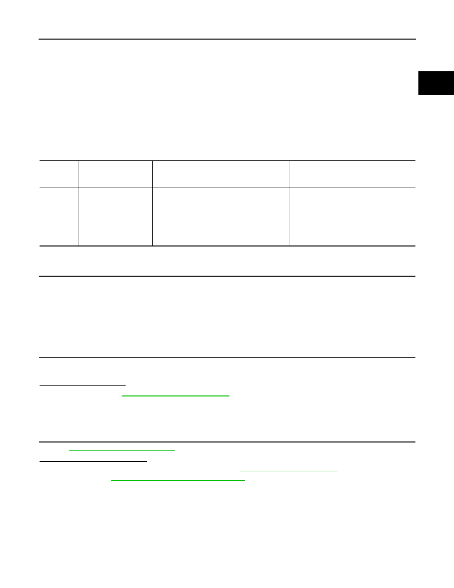
DTC No.
Trouble diagnosis name
(Trouble diagnosis con-
tent)
DTC detecting condition
Possible cause
P0460
FUEL LEV SEN SLOSH
(Fuel level sensor circuit
noise)
Even though the vehicle is parked, a signal be-
ing varied is sent from the fuel level sensor to
ECM.
• Harness or connectors
(The CAN communication line is open or
shorted)
• Harness or connectors
(The sensor circuit is open or shorted)
• Combination meter
• Fuel level sensor