Nissan Juke F15. Manual - part 390


  Index      Nissan     Nissan Juke F15 (2015 year) - Service and Repair Manual


Search            


Content   ..  388  389  390  391   ..


Nissan Juke F15. Manual - part 390


P0448 EVAP CANISTER VENT CONTROL VALVE

EC-373

< DTC/CIRCUIT DIAGNOSIS >

[MR FOR NISMO RS MODELS]

C

D

E

F

G

H

I

J

K

L

M

A

EC

N

P

O

Diagnosis Procedure

INFOID:0000000012197908

1.

CHECK RUBBER TUBE

1. Turn ignition switch OFF.

2. Disconnect rubber tube connected to EVAP canister vent control valve.

3. Check the rubber tube for clogging.
Is the inspection result normal?

YES

>> GO TO 2.

NO

>> Clean rubber tube using an air blower.

2.

CHECK EVAP CANISTER VENT CONTROL VALVE

Check the EVAP canister vent control valve. Refer to 

EC-374, "Component Inspection"

.

Is the inspection result normal?

YES

>> GO TO 3.

NO

>> Replace EVAP canister vent control valve. Refer to 

FL-27, "2WD : Exploded View"

(2WD), 

FL-30,

"AWD : Exploded View"

(AWD).

3.

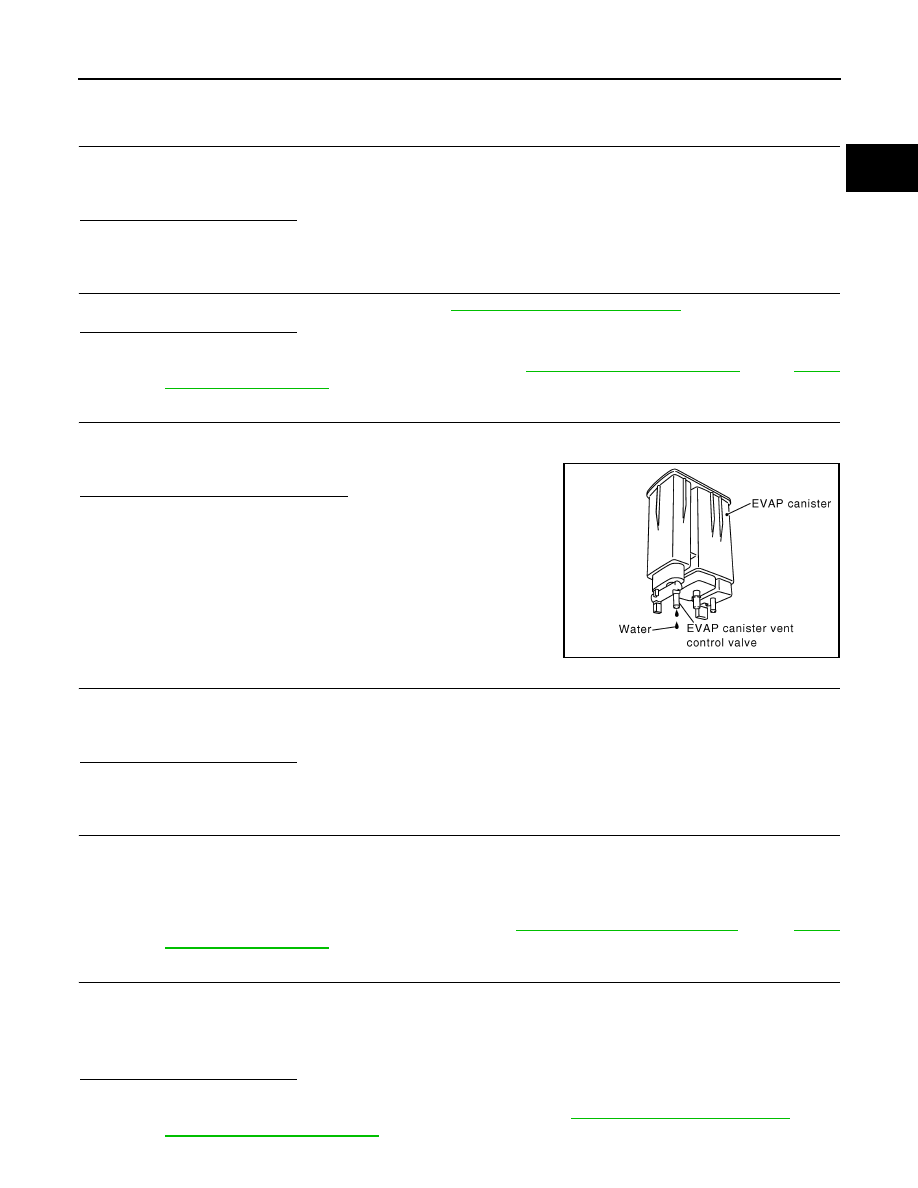
CHECK IF EVAP CANISTER IS SATURATED WITH WATER

1. Remove EVAP canister with EVAP canister vent control valve and EVAP control system pressure sensor

attached.

2. Check if water will drain from the EVAP canister.
Does water drain from EVAP canister?

YES

>> GO TO 4.

NO

>> GO TO 6.

4.

CHECK EVAP CANISTER

Weigh the EVAP canister with the EVAP canister vent control valve and EVAP control system pressure sensor

attached.

The weight should be less than 1.9 kg (4.2 lb).
Is the inspection result normal?

YES

>> GO TO 6.

NO

>> GO TO 5.

5.

DETECT MALFUNCTIONING PART

Check the following.

• EVAP canister for damage

• EVAP hose between EVAP canister and vehicle frame for clogging or poor connection

>> Repair hose or replace EVAP canister. Refer to 

FL-27, "2WD : Exploded View"

(2WD), 

FL-30,

"AWD : Exploded View"

(AWD).

6.

CHECK EVAP CONTROL SYSTEM PRESSURE SENSOR CONNECTOR

1. Disconnect EVAP control system pressure sensor harness connector.

2. Check connectors for water.

Is the inspection result normal?

YES

>> GO TO 7.

NO

>> Replace EVAP control system pressure sensor. Refer to 

FL-27, "2WD : Exploded View"

(2WD),

FL-30, "AWD : Exploded View"

(AWD).

PBIB1213E

Water should not exist.

EC-374

< DTC/CIRCUIT DIAGNOSIS >

[MR FOR NISMO RS MODELS]

P0448 EVAP CANISTER VENT CONTROL VALVE

7.

CHECK EVAP CONTROL SYSTEM PRESSURE SENSOR

Check the EVAP control system pressure sensor. Refer to 

EC-379, "Component Inspection"

.

Is the inspection result normal?

YES

>> Check intermittent incident. Refer to 

GI-45, "Intermittent Incident"

.

NO

>> Replace EVAP control system pressure sensor. Refer to 

FL-27, "2WD : Exploded View"

(2WD),

FL-30, "AWD : Exploded View"

(AWD).

Component Inspection

INFOID:0000000012197909

1.

CHECK EVAP CANISTER VENT CONTROL VALVE-I

1. Turn ignition switch OFF.

2. Remove EVAP canister vent control valve from EVAP canister.

3. Check portion (A) of EVAP canister vent control valve for being

rusted.

Is it rusted?

YES

>> Replace EVAP canister vent control valve. Refer to 

FL-

27, "2WD : Exploded View"

(2WD)

FL-30, "AWD :

Exploded View"

(AWD).

NO

>> GO TO 2.

2.

CHECK EVAP CANISTER VENT CONTROL VALVE-II

With CONSULT

1. Reconnect harness connectors disconnected.

2. Turn ignition switch ON.

3. Perform “VENT CONTROL/V” in “ACTIVE TEST” mode of “ENGINE” using CONSULT.

4. Check air passage continuity and operation delay time.

Make sure new O-ring is installed properly.

Operation takes less than 1 second.

Without CONSULT

Check air passage continuity and operation delay time under the fol-

lowing conditions.

Make sure new O-ring is installed properly.

Operation takes less than 1 second.

Is the inspection result normal?

YES

>> GO TO 3.

NO

>> Replace EVAP canister vent control valve. Refer to 

FL-27, "2WD : Exploded View"

(2WD), 

FL-30,

"AWD : Exploded View"

(AWD).

3.

CHECK EVAP CANISTER VENT CONTROL VALVE-III

With CONSULT

1. Clean the air passage [portion (A) to (B)] of EVAP canister vent control valve using an air blower.

JMBIA0168ZZ

Condition

(VENT CONT/V)

Air passage continuity between (A) and (B)

ON

Not existed

OFF

Existed

Condition

Air passage continuity between (A) and (B)

12 V direct current supply between 
terminals (1) and (2)

Not existed

OFF

Existed

JMBIA0169ZZ

P0448 EVAP CANISTER VENT CONTROL VALVE

EC-375

< DTC/CIRCUIT DIAGNOSIS >

[MR FOR NISMO RS MODELS]

C

D

E

F

G

H

I

J

K

L

M

A

EC

N

P

O

2. Perform “VENT CONTROL/V” in “ACTIVE TEST” mode of “ENGINE” using CONSULT.

3. Check air passage continuity and operation delay time.

Make sure new O-ring is installed properly.

Operation takes less than 1 second.

Without CONSULT

1. Clean the air passage [portion (A) to (B)] of EVAP canister vent

control valve using an air blower.

2. Check air passage continuity and operation delay time under the following conditions.

Make sure new O-ring is installed properly.

Operation takes less than 1 second.

Is the inspection result normal?

YES

>> INSPECTION END

NO

>> Replace EVAP canister vent control valve. Refer to 

FL-27, "2WD : Exploded View"

(2WD), 

FL-30,

"AWD : Exploded View"

(AWD).

Condition

(VENT CONT/V)

Air passage continuity between (A) and (B)

ON

Not existed

OFF

Existed

Condition

Air passage continuity between (A) and (B)

12 V direct current supply between
 terminals (1) and (2)

Not existed

OFF

Existed

JMBIA0169ZZ

EC-376

< DTC/CIRCUIT DIAGNOSIS >

[MR FOR NISMO RS MODELS]

P0451 EVAP CONTROL SYSTEM PRESSURE SENSOR

P0451 EVAP CONTROL SYSTEM PRESSURE SENSOR

DTC Logic

INFOID:0000000012197910

DTC DETECTION LOGIC

NOTE:

If DTC P0451 is displayed with DTC P0643, first perform the trouble diagnosis for DTC P0643. Refer to

EC-424, "DTC Logic"

.

DTC CONFIRMATION PROCEDURE

NOTE:

Never remove fuel filler cap during DTC confirmation procedure.

1.

PRECONDITIONING

If DTC Confirmation Procedure has been previously conducted, always perform the following procedure

before conducting the next test. 

1. Turn ignition switch OFF and wait at least 10 seconds.

2. Turn ignition switch ON.

3. Turn ignition switch OFF and wait at least 10 seconds.

With CONSULT>>GO TO 2.
Without CONSULT>>GO TO 5.

2.

PERFORM DTC CONFIRMATION PROCEDURE-1

With CONSULT

1. Start engine and let it idle for least 40 seconds.

NOTE:

Do not depress accelerator pedal even slightly.

2. Check 1st trip DTC.
Is 1st trip DTC detected?

YES

>> Proceed to 

EC-377, "Diagnosis Procedure"

.

NO

>> GO TO 3.

3.

PERFORM DTC CONFIRMATION PROCEDURE-2

With CONSULT

1. Select “EVAP DIAG READY” in “DATA MONITOR” mode of “ENGINE”.

2. Let it idle until “OFF” of “EVAP DIAG READY” changes to “ON”.

NOTE:

It will take at most 2 hours until “OFF” of “EVAP DIAG READY” changes to “ON”.

3. Turn ignition switch OFF and wait at least 90 minutes.

NOTE:

Never turn ignition switch ON during 90 minutes.

4. Turn ignition switch ON.

5. Select “EVAP LEAK DIAG” in “DATA MONITOR” mode of “ENGINE”.

6. Check that “EVAP LEAK DIAG” indication.
Which is displayed on CONSULT?

CMPLT >> GO TO 4.

YET

>> 1. Perform DTC CONFIRMATION PROCEDURE again.

2. GO TO 1.

DTC No.

Trouble diagnosis name

(Trouble diagnosis con-

tent)

DTC detecting condition

Possible cause

P0451

EVAP SYS PRES SEN
(EVAP control system 
pressure sensor perfor-
mance)

ECM detects a sloshing signal from the EVAP 
control system pressure sensor

• Harness or connectors

(EVAP control system pressure sensor 
circuit is shorted.)

• EVAP control system pressure sensor


Content   ..  388  389  390  391   ..