Nissan Juke F15. Manual - part 383


  Index      Nissan     Nissan Juke F15 (2015 year) - Service and Repair Manual


Search            


Content   ..  381  382  383  384   ..


Nissan Juke F15. Manual - part 383


P0335 CKP SENSOR (POS)

EC-345

< DTC/CIRCUIT DIAGNOSIS >

[MR FOR NISMO RS MODELS]

C

D

E

F

G

H

I

J

K

L

M

A

EC

N

P

O

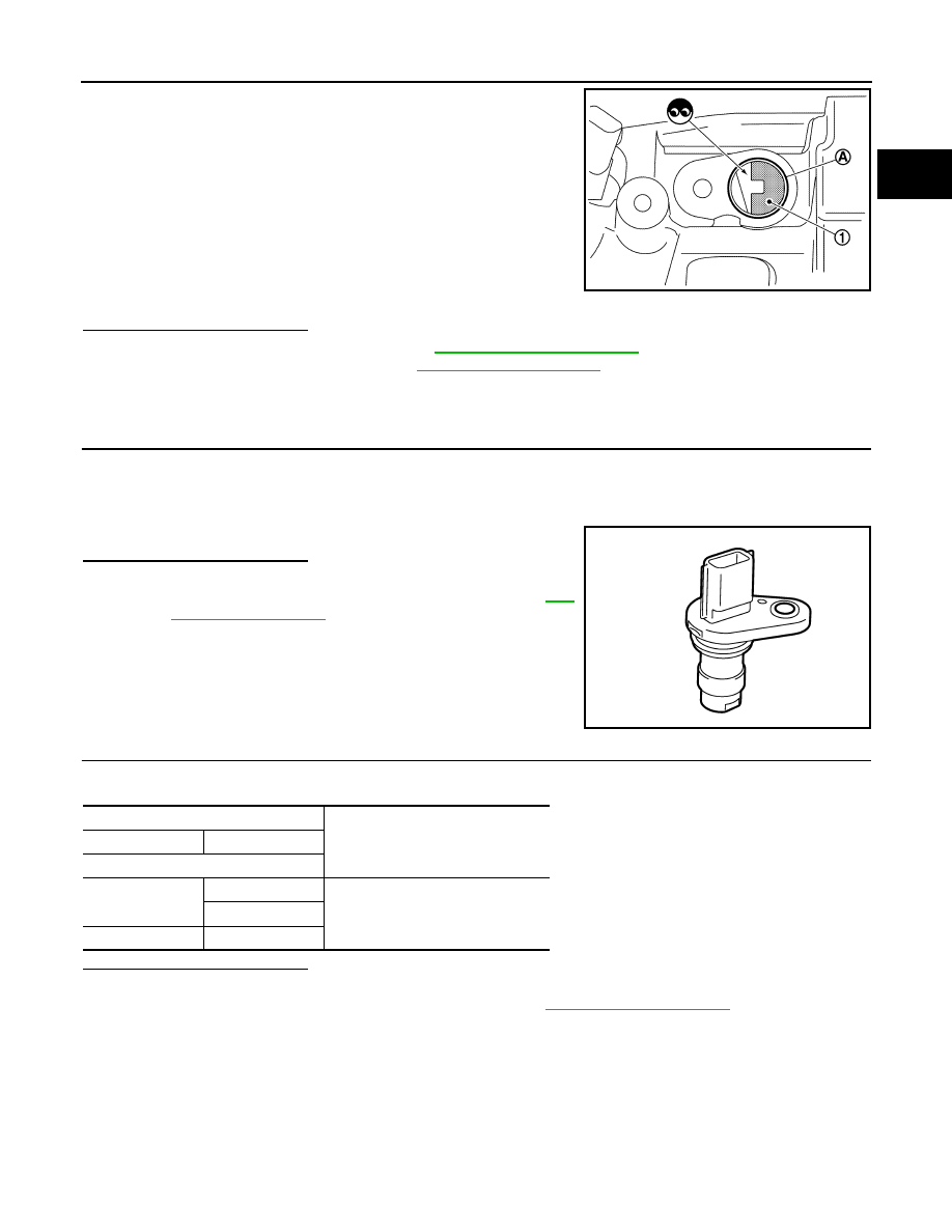
2. Look into the mounting hole (A) of the crankshaft position sensor

(POS) to check that there is no missing gear tooth in the signal

plate (1).

Is the inspection result normal?

YES

>> Check intermittent incident. Refer to 

GI-45, "Intermittent Incident"

.

NO

>> Replace the signal plate. Refer to 

EM-114, "Exploded View"

.

Component Inspection

INFOID:0000000012197888

1.

CHECK CRANKSHAFT POSITION SENSOR (POS)-I

1. Turn ignition switch OFF.

2. Loosen the fixing bolt of the sensor.

3. Disconnect crankshaft position sensor (POS) harness connector.

4. Remove the sensor.

5. Visually check the sensor for chipping.
Is the inspection result normal?

YES

>> GO TO 2.

NO

>> Replace crankshaft position sensor (POS). Refer to 

EM-

114, "Exploded View"

.

2.

CHECK CRANKSHAFT POSITION SENSOR (POS)-II

Check the resistance between crankshaft position sensor (POS) terminals as per the following.

Is the inspection result normal?

YES

>> INSPECTION END

NO

>> Replace crankshaft position sensor (POS). Refer to 

EM-114, "Exploded View"

.

JPBIA4623ZZ

PBIA9209J

Crankshaft position sensor (POS)

Resistance [at 25

°C (77°F)]

+

Terminal (Polarity)

1

2

Except 0 or 

∞ Ω

3

2

3

EC-346

< DTC/CIRCUIT DIAGNOSIS >

[MR FOR NISMO RS MODELS]

P0340 CMP SENSOR (PHASE)

P0340 CMP SENSOR (PHASE)

DTC Logic

INFOID:0000000012197889

DTC DETECTION LOGIC

DTC CONFIRMATION PROCEDURE

1.

PRECONDITIONING

If DTC Confirmation Procedure has been previously conducted, always perform the following procedure

before conducting the next test.

1. Turn ignition switch OFF and wait at least 10 seconds.

2. Turn ignition switch ON.

3. Turn ignition switch OFF and wait at least 10 seconds.

TESTING CONDITION:

Before performing the following procedure, confirm that battery voltage is more than 10.5 V with igni-

tion switch ON.

>> GO TO 2.

2.

PERFORM DTC CONFIRMATION PROCEDURE-I

1. Start engine and let it idle for at least 5 seconds.

If engine does not start, crank engine for at least 2 seconds.

2. Check 1st trip DTC.
Is 1st trip DTC detected?

YES

>> Proceed to 

EC-347, "Diagnosis Procedure"

.

NO

>> GO TO 3.

3.

PERFORM DTC CONFIRMATION PROCEDURE-I

DTC No.

Trouble diagnosis name

(Trouble diagnosis con-

tent)

DTC detecting condition

Possible cause

P0340

CMP SEN/CIRC-B1
[Camshaft position sen-
sor (PHASE) circuit]

• The cylinder No. signal is not sent to ECM for 

the first few seconds during engine cranking.

• The cylinder No. signal is not sent to ECM 

during engine running.

• The cylinder No. signal is not in the normal 

pattern during engine running.

• Harness or connectors

(Camshaft position sensor circuit is open 
or shorted)
(Fuel rail pressure sensor circuit is open 
or shorted.)
(Battery current sensor circuit is open or 
shorted.)
(G sensor circuit is open or shorted.) 
(Exhaust valve timing control position 
sensor circuit is open or shorted.)
(Accelerator pedal position sensor 2 cir-
cuit is open or shorted.)
(Turbocharger boost sensor circuit is 
open or shorted.)
(Engine oil pressure sensor circuit is 
open or shorted.)

• Camshaft position sensor
• Camshaft (Intake)
• Starter motor
• Starting system circuit
• Dead (Weak) battery
• Fuel rail pressure sensor
• Battery current sensor
• G sensor
• Exhaust valve timing control position sen-

sor

• Accelerator pedal position sensor 2
• Turbocharger boost sensor
• Engine oil pressure sensor

P0340 CMP SENSOR (PHASE)

EC-347

< DTC/CIRCUIT DIAGNOSIS >

[MR FOR NISMO RS MODELS]

C

D

E

F

G

H

I

J

K

L

M

A

EC

N

P

O

1. Maintaining engine speed at more than 800 rpm for at least 5 seconds.

2. Check 1st trip DTC.
Is 1st trip DTC detected?

YES

>> Proceed to 

EC-347, "Diagnosis Procedure"

.

NO

>> INSPECTION END

Diagnosis Procedure

INFOID:0000000012197890

1.

CHECK STARTING SYSTEM

Turn ignition switch to START position.
Does the engine turn over? Does the starter motor operate?

YES

>> GO TO 2.

NO

>> Check starting system (Refer to 

STR-18, "Work Flow (With GR8-1200 NI)"

 or 

STR-21, "Work Flow

(Without GR8-1200 NI)"

. For the details of the GR8-1200 NI, refer to 

STR-4, "Special Service

Tools"

.).

2.

CHECK CAMSHAFT POSITION (CMP) SENSOR (PHASE) POWER SUPPLY

1. Turn ignition switch OFF.

2. Disconnect camshaft position (CMP) sensor (PHASE) harness connector.

3. Turn ignition switch ON.

4. Check the voltage between CMP sensor (PHASE) harness connector and ground.

Is the inspection result normal?

YES

>> GO TO 4.

NO

>> GO TO 3.

3.

CHECK SENSOR POWER SUPPLY CIRCUIT

1. Turn ignition switch OFF.

2. Disconnect ECM harness connector.

3. Check harness connector for short to power and short to ground, between the following terminals.

Is inspection result normal?

YES

>> Perform the trouble diagnosis for power supply circuit.

NO

>> Repair or replace error-detected parts.

4.

CHECK CMP SENSOR (PHASE) GROUND CIRCUIT

1. Turn ignition switch OFF.

2. Disconnect ECM harness connector.

3. Check the continuity between CMP sensor (PHASE) harness connector and ECM harness connector.

+

Voltage

(Approx.)

CMP sensor (PHASE)

Connector

Terminal

F109

1

Ground

5 V

ECM

Sensor

Connector

Terminal

Name

Connector

Terminal

F25

39

FRP sensor

F5

1

EOP sensor

F43

3

Turbocharger boost sensor

F75

1

F26

68

Battery current sensor

F52

1

G sensor

B32

3

72

CMP sensor

F109

1

EVT control position sensor

F110

1

E18

118

APP sensor 2

E101

5

EC-348

< DTC/CIRCUIT DIAGNOSIS >

[MR FOR NISMO RS MODELS]

P0340 CMP SENSOR (PHASE)

4. Also check harness for short to power.
Is the inspection result normal?

YES

>> GO TO 5.

NO

>> Repair or replace error-detected parts.

5.

CHECK CMP SENSOR (PHASE) INPUT SIGNAL CIRCUIT

1. Disconnect ECM harness connector.

2. Check the continuity between CMP sensor (PHASE) harness connector and ECM harness connector.

3. Also check harness for short to ground and to power.
Is the inspection result normal?

YES

>> GO TO 6.

NO

>> Repair or replace error-detected parts.

6.

CHECK CAMSHAFT POSITION SENSOR (PHASE)

Check the camshaft position sensor (PHASE). Refer to 

EC-348, "Component Inspection"

.

Is the inspection result normal?

YES

>> GO TO 7.

NO

>> Replace camshaft position sensor (PHASE). Refer to 

EM-89, "Removal and Installation"

.

7.

CHECK CAMSHAFT (INT)

Check the following.

• Accumulation of debris to the signal plate of camshaft rear end

• Chipping signal plate of camshaft rear end
Is the inspection result normal?

YES

>> Check intermittent incident. Refer to 

GI-45, "Intermittent

Incident"

.

NO

>> Remove debris and clean the signal plate of camshaft

rear end or replace camshaft. Refer to 

EM-89, "Removal

and Installation"

.

Component Inspection

INFOID:0000000012197891

1.

CHECK CAMSHAFT POSITION SENSOR (PHASE)-I

1. Turn ignition switch OFF.

2. Loosen the fixing bolt of the sensor.

3. Disconnect camshaft position sensor (PHASE) harness connector.

4. Remove the sensor.

+

Continuity

CMP sensor (PHASE)

ECM

Connector

Terminal

Connector

Terminal

F109

2

F26

59

Existed

+

Continuity

CMP sensor (PHASE)

ECM

Connector

Terminal

Connector

Terminal

F109

3

F26

63

Existed

JSBIA0599ZZ


Content   ..  381  382  383  384   ..