Nissan Juke F15. Manual - part 347


  Index      Nissan     Nissan Juke F15 (2015 year) - Service and Repair Manual


Search            


Content   ..  345  346  347  348   ..


Nissan Juke F15. Manual - part 347


P0014 EVT CONTROL

EC-201

< DTC/CIRCUIT DIAGNOSIS >

[MR FOR NISMO RS MODELS]

C

D

E

F

G

H

I

J

K

L

M

A

EC

N

P

O

Check the following.

• Accumulation of debris to the signal plate of camshaft rear end

• Chipping signal plate of camshaft rear end
Is the inspection result normal?

YES

>> GO TO 6.

NO

>> Remove debris and clean the signal plate of camshaft

rear end or replace camshaft. Refer to 

EM-89, "Removal

and Installation"

.

6.

CHECK TIMING CHAIN INSTALLATION

Check service records for any recent repairs that may cause timing chain misaligned.
Are there any service records that may cause timing chain misaligned?

YES

>> Check timing chain installation. Refer to 

EM-77, "Removal and Installation"

.

NO

>> GO TO 7.

7.

CHECK LUBRICATION CIRCUIT

Refer to 

EM-92, "Inspection"

.

Is the inspection result normal?

YES

>> Check intermittent incident. Refer to 

GI-45, "Intermittent Incident"

.

NO

>> Clean lubrication line.

Component Inspection

INFOID:0000000012197757

1.

CHECK EXHAUST VALVE TIMING CONTROL SOLENOID VALVE-I

1. Turn ignition switch OFF.

2. Disconnect exhaust valve timing control solenoid valve harness connector.

3. Check resistance between exhaust valve timing control solenoid valve terminals as per the following.

Is the inspection result normal?

YES

>> GO TO 2.

NO

>> Replace exhaust valve timing control solenoid valve. Refer to 

EM-76, "Exploded View"

.

2.

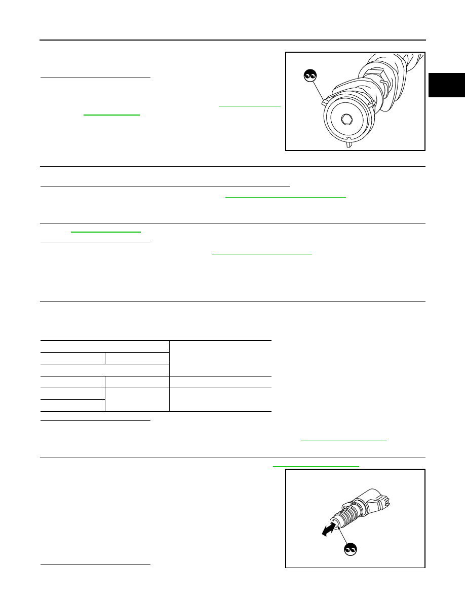
CHECK EXHAUST VALVE TIMING CONTROL SOLENOID VALVE-II

1. Remove exhaust valve timing control solenoid valve. Refer to 

EM-76, "Exploded View"

.

2. Provide 12 V DC between exhaust valve timing control solenoid

valve terminals 1 and 2, and then interrupt it. Check that the

plunger moves as shown in the figure.

CAUTION:

Do not apply 12 V DC continuously for 5 seconds or more.

Doing so may result in damage to the coil in exhaust valve

timing control solenoid valve.

NOTE:

Always replace O-ring when exhaust valve timing control

solenoid valve is removed.

Is the inspection result normal?

YES

>> INSPECTION END

JMBIA0059ZZ

Exhaust valve timing control solenoid valve

Resistance

+

Terminal

1

 2

7.0 - 7.7 

Ω [at 20°C (68°F)]

1

Ground

∞ Ω

(Continuity should not exist)

2

JMBIA0079ZZ

EC-202

< DTC/CIRCUIT DIAGNOSIS >

[MR FOR NISMO RS MODELS]

P0014 EVT CONTROL

NO

>> Replace exhaust valve timing control solenoid valve. Refer to 

EM-76, "Exploded View"

.

P0030, P0031, P0032 A/F SENSOR 1 HEATER

EC-203

< DTC/CIRCUIT DIAGNOSIS >

[MR FOR NISMO RS MODELS]

C

D

E

F

G

H

I

J

K

L

M

A

EC

N

P

O

P0030, P0031, P0032 A/F SENSOR 1 HEATER

DTC Logic

INFOID:0000000012197758

DTC DETECTION LOGIC

DTC CONFIRMATION PROCEDURE

1.

PRECONDITIONING

If DTC Confirmation Procedure has been previously conducted, always perform the following procedure

before conducting the next test.

1. Turn ignition switch OFF and wait at least 10 seconds.

2. Turn ignition switch ON.

3. Turn ignition switch OFF and wait at least 10 seconds.

TESTING CONDITION:

Before performing the following procedure, confirm that battery voltage is more than between 11 V at

idle.

>> GO TO 2.

2.

PERFORM DTC CONFIRMATION PROCEDURE

1. Start engine and let it idle for at least 10 seconds.

2. Check 1st trip DTC.
Is 1st trip DTC detected?

YES

>> Proceed to 

EC-203, "Diagnosis Procedure"

.

NO

>> INSPECTION END

Diagnosis Procedure

INFOID:0000000012197759

1.

CHECK AIR FUEL RATIO (A/F) SENSOR 1 POWER SUPPLY CIRCUIT

1. Disconnect air fuel ratio (A/F) sensor 1 harness connector.

2. Turn ignition switch ON.

3. Check the voltage between A/F sensor 1 harness connector and ground.

Is the inspection result normal?

YES

>> GO TO 2.

NO

>> Repair or replace error-detected parts.

 DTC No.

Trouble diagnosis name

(Trouble diagnosis con-

tent)

DTC detecting condition

Possible cause

P0030

A/F SEN 1 HTR (B1)
(Air fuel ratio (A/F) sensor 
1 heater control circuit)

Deterioration in A/F sensor 1 heater performance.
(Voltage signal transmitted from A/F sensor 1 heat-
er to ECM is higher/lower than voltage in the nor-
mal range.)

• Harness or connectors

(A/F sensor 1 heater circuit is open or 
shorted.)

• A/F sensor 1 heater

P0031

A/F SEN 1 HTR (B1)
(Air fuel ratio (A/F) sensor 
1 heater control circuit low)

The current amperage in the A/F sensor 1 heater 
circuit is out of the normal range.
(An excessively low voltage signal is sent to ECM 
through the A/F sensor 1 heater.)

P0032

A/F SEN 1 HTR (B1)
(Air fuel ratio (A/F) sensor 
1 heater control circuit 
high)

The current amperage in the A/F sensor 1 heater 
circuit is out of the normal range.
(An excessively high voltage signal is sent to ECM 
through the A/F sensor 1 heater.)

• Harness or connectors

(A/F sensor 1 heater circuit is short-
ed.)

• A/F sensor 1 heater

+

Voltage

A/F sensor 1

Connector

Terminal

F70

4

Ground

Battery voltage

EC-204

< DTC/CIRCUIT DIAGNOSIS >

[MR FOR NISMO RS MODELS]

P0030, P0031, P0032 A/F SENSOR 1 HEATER

2.

CHECK A/F SENSOR 1 HEATER OUTPUT SIGNAL CIRCUIT

1. Turn ignition switch OFF.

2. Disconnect ECM harness connector.

3. Check the continuity between A/F sensor 1 harness connector and ECM harness connector.

4. Also check harness for short to ground and short to power.
Is the inspection result normal?

YES

>> GO TO 3.

NO

>> Repair open circuit, short to ground or short to power in harness or connectors.

3.

CHECK A/F SENSOR 1 HEATER

Check the A/F sensor 1 heater. Refer to 

EC-204, "Component Inspection"

.

Is the inspection result normal?

YES

>> Check intermittent incident. Refer to 

GI-45, "Intermittent Incident"

.

NO

>> GO TO 4.

4.

REPLACE AIR FUEL RATIO (A/F) SENSOR 1

Replace malfunctioning air fuel ratio (A/F) sensor 1. Refer to 

EM-44, "Exploded View"

.

CAUTION:

• Discard any A/F sensor which has been dropped from a height of more than 0.5 m (19.7 in) onto a

hard surface such as a concrete floor; use a new one.

• Before installing new A/F sensor, clean exhaust system threads using Oxygen Sensor Thread

Cleaner [commercial service tool (J-43897-18 or J-43897-12)] and approved Anti-seize Lubricant

(commercial service tool).

>> INSPECTION END

Component Inspection

INFOID:0000000012197760

1.

CHECK AIR FUEL RATIO (A/F) SENSOR 1

1. Turn ignition switch OFF.

2. Disconnect A/F sensor 1 harness connector.

3. Check resistance between A/F sensor 1 terminals as per the following.

Is the inspection result normal?

YES

>> INSPECTION END

NO

>> GO TO 2.

2.

REPLACE AIR FUEL RATIO (A/F) SENSOR 1

Replace air fuel ratio (A/F) sensor 1. Refer to 

EM-44, "Exploded View"

.

CAUTION:

+

Continuity

A/F sensor 1

ECM

Connector

Terminal

Connector

Terminal

F70

3

E18

125

Existed

A/F sensor 1

Resistance

+

Terminal

3

4

1.8 - 2.44 

Ω [at 20°C (68°F)]

1

∞ Ω

(Continuity should not exist)

2

4

1

2


Content   ..  345  346  347  348   ..