Nissan Juke F15. Manual - part 344
POWER SUPPLY AND GROUND CIRCUIT
EC-189
< DTC/CIRCUIT DIAGNOSIS >
[MR FOR NISMO RS MODELS]
C
D
E
F
G
H
I
J
K
L
M
A
EC
N
P
O
Is the inspection result normal?
YES
>> Replace IPDM E/R. Refer to
PCS-37, "Removal and Installation"
.
NO
>> Repair or replace error-detected parts.
9.
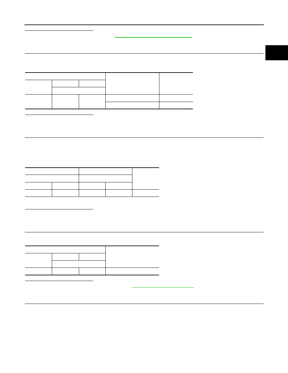
CHECK IGNITION SWITCH SIGNAL
1. Turn ignition switch ON.
2. Check the voltage between ECM harness connector terminals.
Is the inspection result normal?
YES
>> GO TO 11.
NO
>> GO TO 10.
10.
CHECK IGNITION SWITCH SIGNAL CIRCUIT
1. Turn ignition switch OFF.
2. Disconnect ECM harness connector.
3. Disconnect IPDM E/R harness connector.
4. Check the continuity between ECM harness connector and IPDM E/R harness connector.
5. Also check harness for short to ground and to power.
Is the inspection result normal?
YES
>> Perform the trouble diagnosis for power supply circuit.
NO
>> Repair or replace error-detected parts.
11.
CHECK ECM POWER SUPPLY (BACK-UP)
Check the voltage between ECM harness connector terminals.
Is the inspection result normal?
YES
>> Check Intermittent Incident. Refer to
GI-45, "Intermittent Incident"
NO
>> GO TO 12.
12.
CHECK ECM POWER SUPPLY (BACK-UP) CIRCUIT
1. Turn ignition switch OFF.
2. Disconnect ECM harness connector.
3. Disconnect IPDM E/R harness connector.
4. Check the continuity between ECM harness connector and IPDM E/R harness connector.
ECM
Condition
Voltage
(Approx.)
Connector
+
−
Terminal
E18
109
127
Ignition switch OFF
0 V
Ignition switch ON
Battery voltage
+
−
Continuity
ECM
IPDM E/R
Connector
Terminal
Connector
Terminal
E18
109
E15
62
Existed
ECM
Voltage
Connector
+
−
Terminal
E18
106
127
Battery voltage