Nissan Juke F15. Manual - part 342
TROUBLE DIAGNOSIS - SPECIFICATION VALUE
EC-181
< DTC/CIRCUIT DIAGNOSIS >
[MR FOR NISMO RS MODELS]
C
D
E
F
G
H
I
J
K
L
M
A
EC
N
P
O
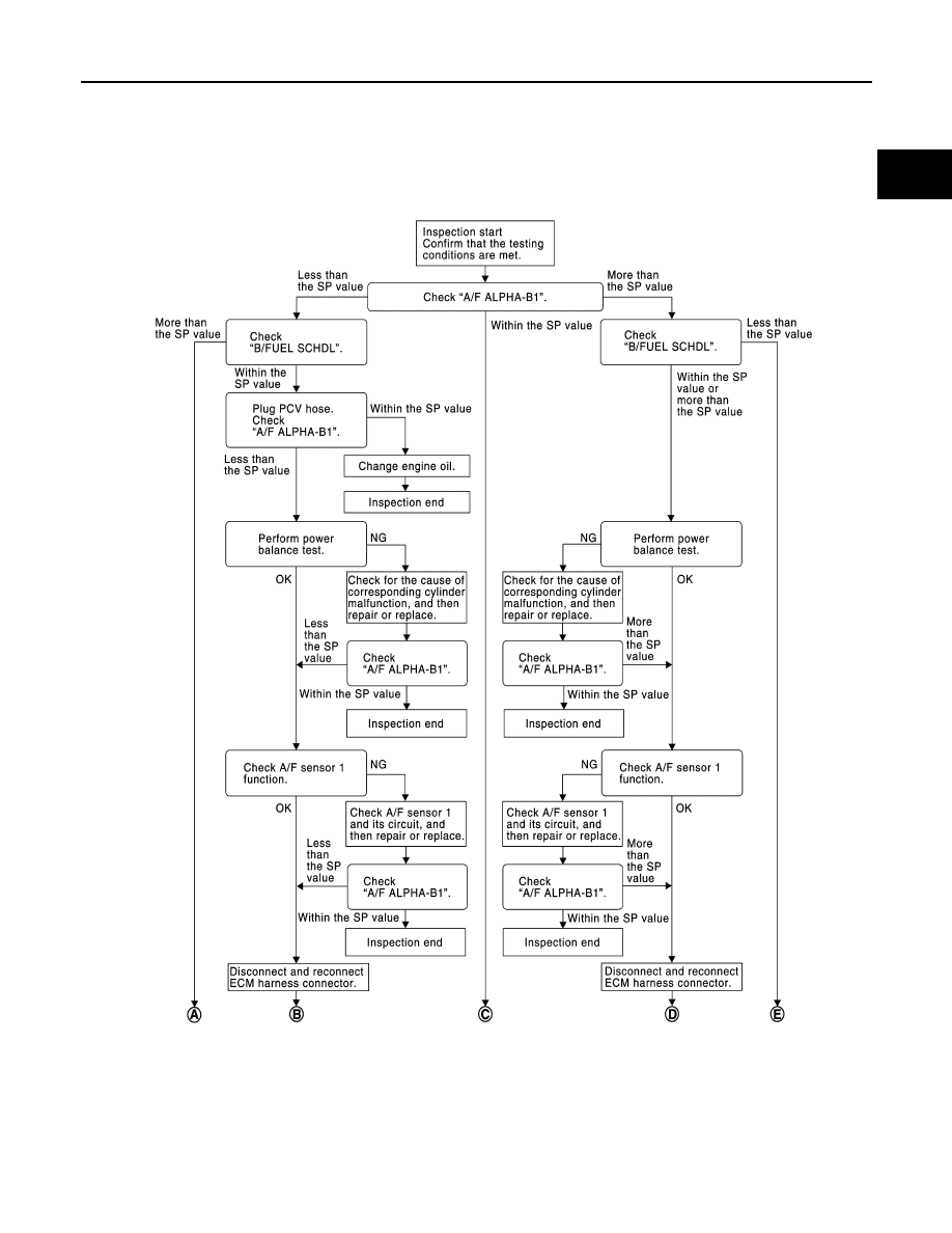
Diagnosis Procedure
INFOID:0000000012197739
OVERALL SEQUENCE
JSBIA1063GB
|
|
|
TROUBLE DIAGNOSIS - SPECIFICATION VALUE EC-181 < DTC/CIRCUIT DIAGNOSIS > [MR FOR NISMO RS MODELS] C D E F G H I J K L M A EC N P O Diagnosis Procedure INFOID:0000000012197739 OVERALL SEQUENCE JSBIA1063GB |