Nissan Juke F15. Manual - part 312
SYSTEM
EC-61
< SYSTEM DESCRIPTION >
[MR FOR NISMO RS MODELS]
C
D
E
F
G
H
I
J
K
L
M
A
EC
N
P
O
ENGINE PROTECTION CONTROL AT LOW ENGINE OIL PRESSURE
ENGINE PROTECTION CONTROL AT LOW ENGINE OIL PRESSURE : System Dia-
gram
INFOID:0000000012197678
ENGINE PROTECTION CONTROL AT LOW ENGINE OIL PRESSURE : System De-
scription
INFOID:0000000012197679
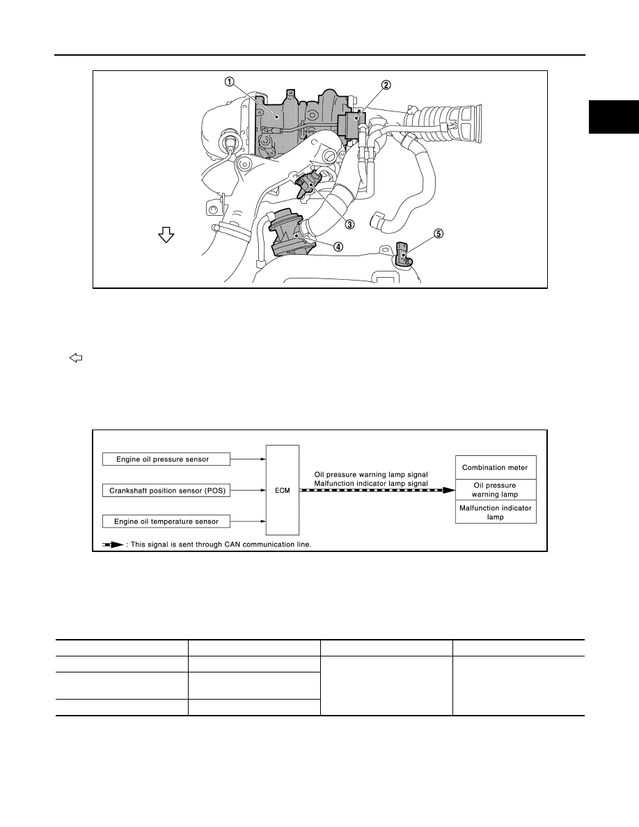
INPUT/OUTPUT SIGNAL CHART
SYSTEM DESCRIPTION
• The engine protection control at low engine oil pressure warns the driver of a decrease in engine oil pres-
sure by the oil pressure warning lamp a before the engine becomes damaged.
• When detecting a decrease in engine oil pressure at an engine speed less than 1,000 rpm, ECM transmits
an oil pressure warning lamp signal to the combination meter.The combination meter turns ON the oil pres-
sure warning lamp, according to the signal.
1.
Turbocharger
2.
Boost control actuator
3.
Turbocharger boost control solenoid
valve
4.
Recirculation valve
5.
Turbocharger boost sensor
(with intake air temperature sensor 2)
: Vehicle front
JPBIA4717ZZ
JPBIA4922GB
Sensor
Input signal to ECM
ECM function
Actuator
Engine oil pressure sensor
Engine pressure
Engine protection control
• Oil pressure warning lamp
signal
• FUel cut control
Combination meter
• Oil pressure warning lamp
Crankshaft position sensor
(POS)
Engine speed
Engine oil temperature sensor
Engine oil temperature