Nissan Juke F15. Manual - part 305


  Index      Nissan     Nissan Juke F15 (2015 year) - Service and Repair Manual


Search            


Content   ..  303  304  305  306   ..


Nissan Juke F15. Manual - part 305


COMPONENT PARTS

EC-33

< SYSTEM DESCRIPTION >

[MR FOR NISMO RS MODELS]

C

D

E

F

G

H

I

J

K

L

M

A

EC

N

P

O

ECM

INFOID:0000000012197626

The ECM consists of a microcomputer and connectors for signal

input and output and for power supply. The ECM controls the engine.

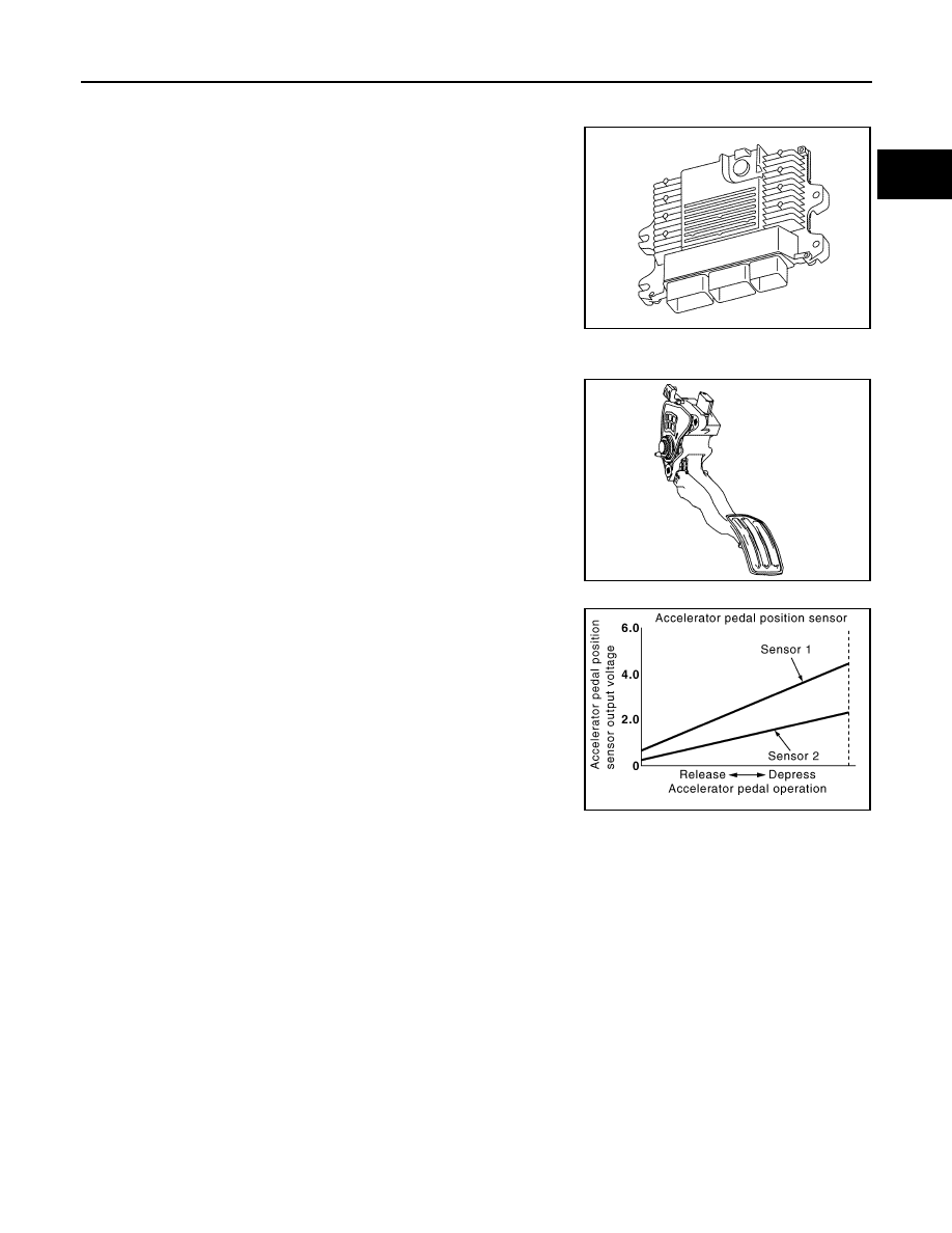
Accelerator Pedal Position Sensor

INFOID:0000000012197627

The accelerator pedal position sensor is installed on the upper end

of the accelerator pedal assembly. The sensor detects the accelera-

tor position and sends a signal to the ECM.

Accelerator pedal position sensor has two sensors. These sensors

are a kind of potentiometers which transform the accelerator pedal

position into output voltage, and emit the voltage signal to the ECM.

In addition, these sensors detect the opening and closing speed of

the accelerator pedal and feed the voltage signals to the ECM. The

ECM judges the current opening angle of the accelerator pedal from

these signals and controls the throttle control motor based on these

signals.

Idle position of the accelerator pedal is determined by the ECM

receiving the signal from the accelerator pedal position sensor. The

ECM uses this signal for the engine operation such as fuel cut.

Electric Throttle Control Actuator

INFOID:0000000012197628

OUTLINE

JPBIA4618ZZ

JPBIA4615ZZ

PBIB1741E

EC-34

< SYSTEM DESCRIPTION >

[MR FOR NISMO RS MODELS]

COMPONENT PARTS

Electric throttle control actuator consists of throttle body, throttle valve, throttle control motor and throttle posi-

tion sensor.

THROTTLE CONTROL MOTOR RELAY

Power supply for the throttle control motor is provided to the ECM via throttle control motor relay. The throttle

control motor relay is ON/OFF controlled by the ECM. When the ignition switch is turned ON, the ECM sends

an ON signal to throttle control motor relay and battery voltage is provided to the ECM. When the ignition

switch is turned OFF, the ECM sends an OFF signal to throttle control motor relay and battery voltage is not

provided to the ECM.

THROTTLE CONTROL MOTOR

The throttle control motor is operated by the ECM and it opens and closes the throttle valve.

The current opening angle of the throttle valve is detected by the throttle position sensor and it provides feed-

back to the ECM to control the throttle control motor to make the throttle valve opening angle properly in

response to driving condition.

THROTTLE POSITION SENSOR

The throttle position sensor responds to the throttle valve movement.

The throttle position sensor has two sensors. These sensors are a

kind of potentiometers which transform the throttle valve position into

output voltage, and emit the voltage signal to the ECM. In addition,

these sensors detect the opening and closing speed of the throttle

valve and feed the voltage signals to the ECM. The ECM judges the

current opening angle of the throttle valve from these signals and the

ECM controls the throttle control motor to make the throttle valve

opening angle properly in response to driving condition.

Ignition Coil With Power Transistor

INFOID:0000000012197629

The ignition signal from the ECM is sent to and amplified by the

power transistor. The power transistor turns ON and OFF the ignition

coil primary circuit. This ON/OFF operation induces the proper high

voltage in the coil secondary circuit.

JSBIA0270GB

PBIB0145E

JPBIA4613ZZ

COMPONENT PARTS

EC-35

< SYSTEM DESCRIPTION >

[MR FOR NISMO RS MODELS]

C

D

E

F

G

H

I

J

K

L

M

A

EC

N

P

O

Fuel Injector

INFOID:0000000012197630

For the fuel injector, a high pressure fuel injector is used and this

enables a high-pressure fuel injection at a high voltage within a short

time. The ECM is equipped with an injector driver unit and actuates

the fuel injector at a high voltage (approximately 65 V at the maxi-

mum).

High Pressure Fuel Pump

INFOID:0000000012197631

The high pressure fuel pump is activated by the exhaust camshaft.

ECM controls the high pressure fuel pump control solenoid valve built into the high pressure fuel pump and

adjusts the amount of discharge by changing the suction timing of the low pressure fuel.

Operating Description

Operating Chart

JSBIA0287ZZ

JSBIA0285GB

JSBIA0286GB

EC-36

< SYSTEM DESCRIPTION >

[MR FOR NISMO RS MODELS]

COMPONENT PARTS

Fuel Rail Pressure Sensor

INFOID:0000000012197632

The fuel rail pressure (FRP) sensor is placed to the fuel rail and

measures fuel pressure in the fuel rail. The sensor transmits voltage

signal to the ECM. As the pressure increases, the voltage rises. The

ECM controls the fuel pressure in the fuel rail by operating high pres-

sure fuel pump. The ECM uses the signal from fuel rail pressure sen-

sor as a feedback signal.

Low Pressure Fuel Pump

INFOID:0000000012197633

The low pressure fuel pump is integrated with a fuel pressure regula-

tor and a fuel filter. This pump is build into the fuel tank.

Fuel Tank Temperature Sensor

INFOID:0000000012197634

The fuel tank temperature sensor is used to detect the fuel tempera-

ture inside the fuel tank. The sensor modifies a voltage signal from

the ECM. The modified signal returns to the ECM as the fuel temper-

ature input. The sensor uses a thermistor which is sensitive to the

change in temperature. The electrical resistance of the thermistor

decreases as temperature increases.

<Reference data>

*: These data are reference values and are measured between ECM terminals.

Fuel Level Sensor

INFOID:0000000012197635

The fuel level sensor is mounted in the fuel level sensor unit.

The sensor detects a fuel level in the fuel tank and transmits a signal to the combination meter. The combina-

tion meter sends the fuel level sensor signal to the ECM via the CAN communication line.

It consists of two parts, one is mechanical float and the other is variable resistor. Fuel level sensor output volt-

age changes depending on the movement of the fuel mechanical float.

JSBIA0291ZZ

JPBIA4972ZZ

SEF012P

Fluid temperature

[

°C (°F)]

Voltage*

[V]

Resistance

[k

Ω]

20 (68)

3.5

2.3 - 2.7

50 (122)

2.2

0.79 - 0.90


Content   ..  303  304  305  306   ..