Nissan Juke F15. Manual - part 276


  Index      Nissan     Nissan Juke F15 (2015 year) - Service and Repair Manual


Search            


Content   ..  274  275  276  277   ..


Nissan Juke F15. Manual - part 276


RING GEAR SHAFT

DLN-109

< UNIT DISASSEMBLY AND ASSEMBLY >

[TRANSFER: TY21B]

C

E

F

G

H

I

J

K

L

M

A

B

DLN

N

O

P

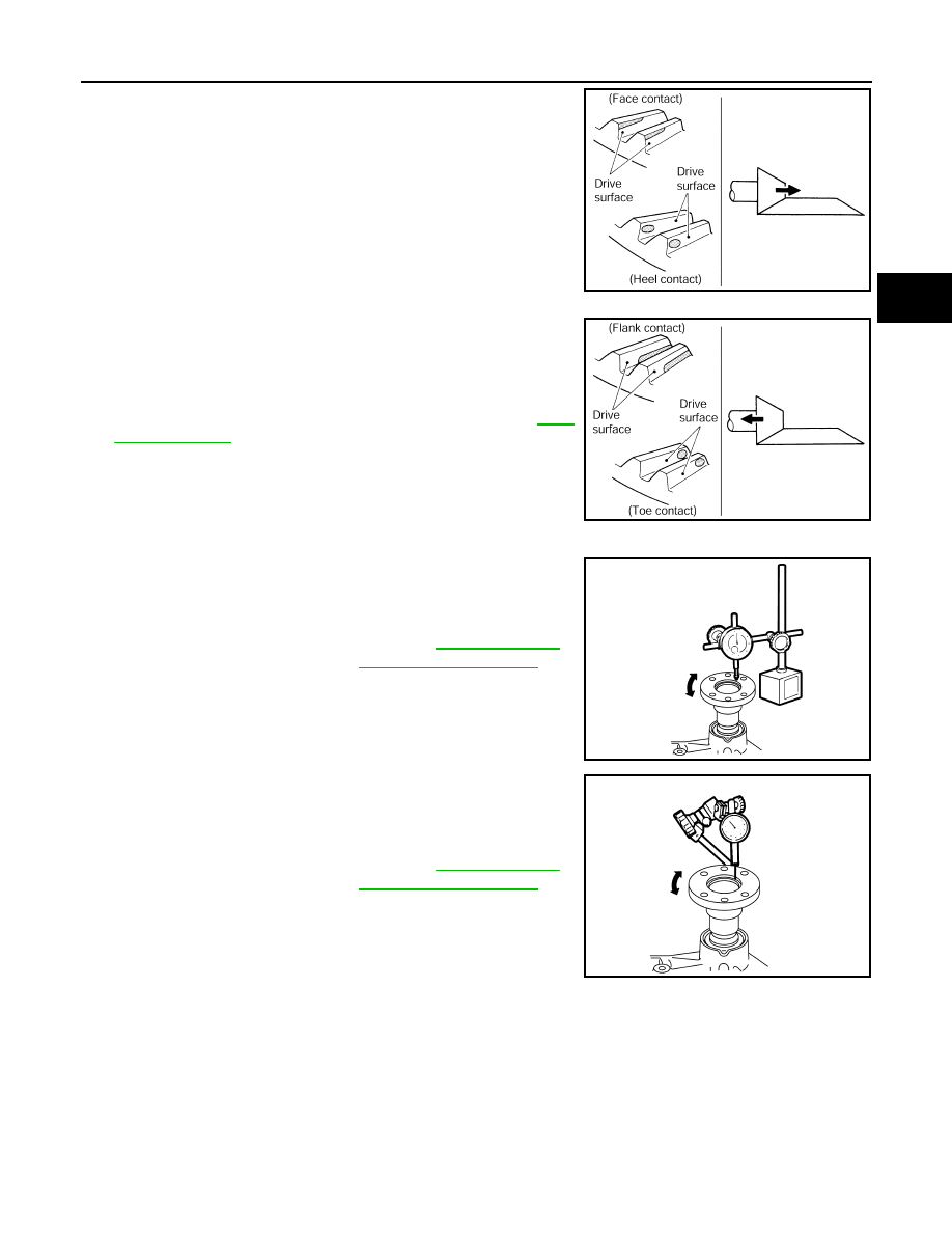
• Thicken the drive pinion adjusting shim to move the drive pin-

ion closer to the ring gear in case of face contact or heel con-

tact.

CAUTION:

Only one adjusting shim can be selected.

• Thin the drive pinion adjusting shim to move the drive pinion

farther from the ring gear in case of flank contact or toe con-

tact.

CAUTION:

Only one adjusting shim can be selected.

9. Reinstall transfer cover for applying liquid gasket. Refer to 

DLN-

117, "Assembly"

.

COMPANION FLANGE RUNOUT

1. Fit a dial indicator onto the companion flange face (inner side of

the propeller shaft bolt holes).

2. Rotate the companion flange to check for runout.

3. Fit a test indicator to the inner side of the companion flange

(socket diameter).

4. Rotate the companion flange to check for runout.

5. Follow the procedure below to adjust if runout value is outside

the repair limit.

CAUTION:

Replace collapsible spacer to check and adjust each part

when companion flange is adjusted or replaced.

a. Check for runout while changing the phase between companion flange and drive pinion in 90

° steps. Then

search for the minimum point.

b. Replace companion flange if runout value is still outside the limit after the phase has been changed.
c. Adjust assembly status of the pinion bearings and drive pinion, or replace drive pinion bearings if runout is

outside the standard after the companion flange is replaced.

Inspection

INFOID:0000000012199469

INSPECTION AFTER DISASSEMBLY

Check items below. If necessary, replace them with new ones.

PDIA0440E

PDIA0441E

Companion flange runout

: Refer to 

DLN-120, "Com-

panion Flange Runout"

.

JSDIA2503ZZ

Companion flange runout

: Refer to 

DLN-120, "Com-

panion Flange Runout"

.

JSDIA2504ZZ

DLN-110

< UNIT DISASSEMBLY AND ASSEMBLY >

[TRANSFER: TY21B]

RING GEAR SHAFT

Gear and Shaft

Check gear face and shaft for wear, cracks, damage, and seizure.

CAUTION:

Replace ring gear and drive pinion as a set (hypoid gear set) if any malfunction is detected on the ring

gear or drive pinion.

Bearing

Check for seizure, peeling, wear, corrosion, sticking, unusual noise, roughness in hand turning, and other

damage.

CAUTION:

Always replace inner race and outer race as a pair when replacing the bearing.

Shim

Check for seizure, damage, and unusual wear.

DRIVE PINION

DLN-111

< UNIT DISASSEMBLY AND ASSEMBLY >

[TRANSFER: TY21B]

C

E

F

G

H

I

J

K

L

M

A

B

DLN

N

O

P

DRIVE PINION

Exploded View

INFOID:0000000012199470

1.

Pinion lock nut

2.

Companion flange

3.

Drive pinion oil seal

4.

Pinion bearing (rear)

5.

Transfer case

6.

Gasket

7.

Filler plug

8.

Collapsible spacer

9.

Drive pinion adjusting shim

10. Pinion bearing (front)

11. Drive pinion

12. Ring gear

13. Ring gear shaft

14. Ring gear bearing (right)

15. Ring gear bearing adjusting shim 

(right)

16. Spacer (right)

17. Transfer case oil seal (right)

18. Drive shaft oil seal

19. Transfer cover

20. Oil defense

21. Ring gear bearing (left)

22. Ring gear bearing adjusting shim 

(left)

23. Spacer (left)

24. Transfer case oil seal (left)

25. Drain plug

26. Dowel pin

A.

Oil seal lip

B.

Transfer case mounting face

: Always replace after every disassembly.

: Select with proper thickness.

: N·m (kg-m, in-lb)

: N·m (kg-m, ft-lb)

: Apply gear oil.

: Apply multi purpose grease

JSDIA2491GB

DLN-112

< UNIT DISASSEMBLY AND ASSEMBLY >

[TRANSFER: TY21B]

DRIVE PINION

Disassembly

INFOID:0000000012199471

1. Remove transfer cover. Refer to 

DLN-117, "Disassembly"

.

2. Remove ring gear shaft assembly. Refer to 

DLN-97, "Disassembly"

.

3. Remove pinion lock nut from the drive pinion.
4. Put matching marks (A) on screw ends of drive pinion and com-

panion flange.

CAUTION:

Use paint to avoid scratching the surface.

5. Remove companion flange from drive pinion with the puller (A)

(Commercial service tool).

6. Remove drive pinion oil seal from the transfer case with the

puller (A) [SST: KV381054S0 (J-34286)].

CAUTION:

Never damage transfer case.

7. Remove drive pinion assembly (1) from transfer case while tap-

ping the drive pinion lightly with a plastic hammer.

CAUTION:

Never drop the drive pinion assembly.

8. Remove collapsible spacer from the drive pinion.
9. Remove inner race of pinion bearing (rear) from transfer case.

: Apply anti-corrosive oil.

: Apply Genuine Silicone RTV or equivalent. Refer to 

GI-22, "Recommended Chemical Products and Sealants"

.

JSDIA2505ZZ

JSDIA2506ZZ

JSDIA2507ZZ

JSDIA2508ZZ


Content   ..  274  275  276  277   ..