Content .. 1360 1361 1362 1363 ..
Nissan Juke F15. Manual - part 1362
WCS
DIAGNOSIS AND REPAIR WORKFLOW
WCS-37
< BASIC INSPECTION >
C
D
E
F
G
H
I
J
K
L
M
B
A
O
P
BASIC INSPECTION
DIAGNOSIS AND REPAIR WORKFLOW
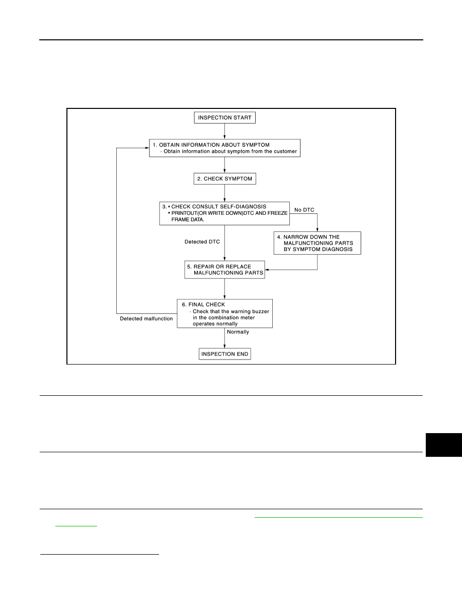
Work Flow
INFOID:0000000012201481
OVERALL SEQUENCE
DETAILED FLOW
1.
OBTAIN INFORMATION ABOUT SYMPTOM
Interview the customer to obtain as much information as possible about the conditions and environment under
which the malfunction occurred.
>> GO TO 2.
2.
CHECK SYMPTOM
• Check the symptom based on the information obtained from the customer.
• Check if any other malfunctions are present.
>> GO TO 3.
3.
CHECK CONSULT SELF-DIAGNOSIS RESULTS
1. Connect CONSULT and perform self-diagnosis. Refer to
WCS-19, "BUZZER : CONSULT Function (BCM
.
2. When DTC is detected, follow the instructions below:
-
Record DTC and Freeze Frame Data.
Are self-diagnosis results normal?
YES
>> GO TO 4.
NO
>> GO TO 5.
JSNIA4492GB