Content .. 1319 1320 1321 1322 ..
Nissan Juke F15. Manual - part 1321
TM-474
< DTC/CIRCUIT DIAGNOSIS >
[CVT: RE0F10D]
P0715 INPUT SPEED SENSOR A
1. Connect all of disconnected connectors.
2. Lift the vehicle.
3. Start the engine.
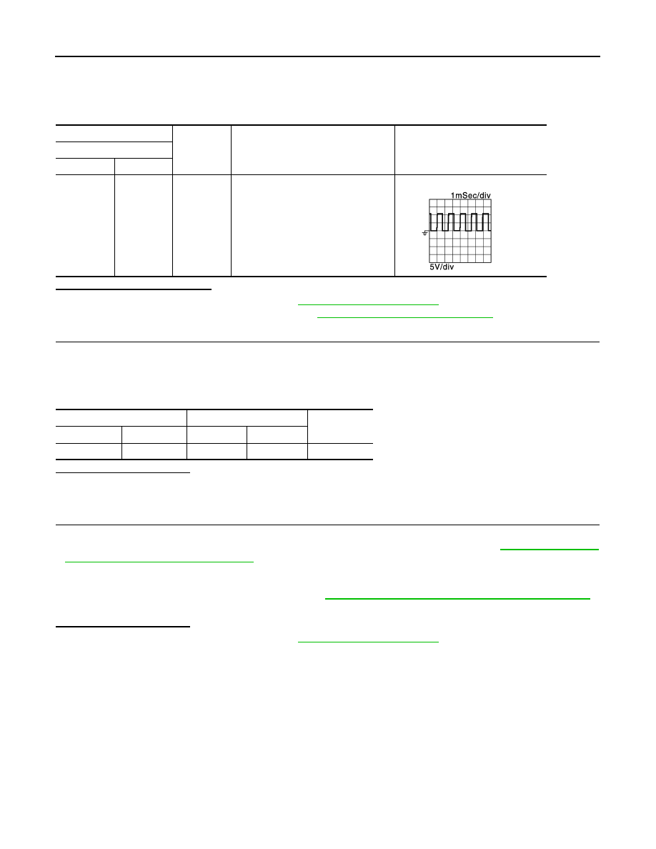
4. Check frequency of primary speed sensor.
Is the inspection result normal?
YES >> Check
intermittent incident. Refer to
GI-45, "Intermittent Incident"
.
NO
>> Replace primary speed sensor. Refer to
TM-562, "Removal and Installation"
6.
CHECK CIRCUIT BETWEEN IPDM E/R AND PRIMARY SPEED SENSOR
1. Turn ignition switch OFF.
2. Disconnect IPDM E/R connector.
3. Check continuity between IPDM E/R harness connector terminal and primary speed sensor harness con-
nector terminal.
Is the check result normal?
YES
>> GO TO 7.
NO
>> Repair or replace malfunctioning parts.
7.
DETECT MALFUNCTIONING ITEMS
Check the following items:
• Open circuit or short circuit in harness between ignition switch and IPDM E/R. Refer to
gram - IGNITION POWER SUPPLY -"
• Short circuit in harness between IPDM E/R harness connector terminal 57 and primary speed sensor har-
ness connector terminal 3.
• 10A fuse (No.55, located in the IPDM E/R). Refer to
PG-80, "Fuse, Connector and Terminal Arrangement"
• IPDM E/R
Is the check result normal?
YES
>> Check intermittent incident. Refer to
GI-45, "Intermittent Incident"
.
NO
>> Repair or replace malfunctioning parts.
+
−
Condition
Frequency
(Approx.)
TCM
Connector
Terminal
F83
35
Ground
• Shift position: “M1” position
• Vehicle speed: 20 km/h (12 MPH)
700 Hz
JSDIA1905GB
IPDM E/R
Primary speed sensor
Continuity
Connector
Terminal
Connector
Terminal
E15
57
F55
3
Existed