Nissan Juke F15. Manual - part 1241


  Index      Nissan     Nissan Juke F15 (2015 year) - Service and Repair Manual


Search            


Content   ..  1239  1240  1241  1242   ..


Nissan Juke F15. Manual - part 1241


TM-154

< PREPARATION >

[CVT: RE0F10B]

PREPARATION

PREPARATION

PREPARATION

Special Service Tool

INFOID:0000000012200849

The actual shapes of TechMate tools may differ from those of special service tools illustrated here.

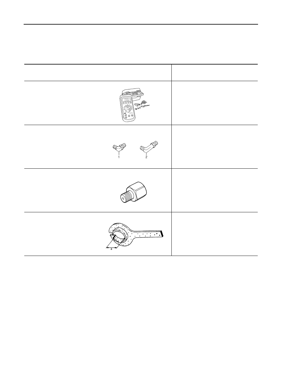
Commercial Service Tool

INFOID:0000000012200850

Tool number
(TechMate No.)
Tool name

Description


(OTC3492)
Oil pressure gauge set

Measuring line pressure

1. ST25054000
(

)

Adapter
2. ST25055000
(

)

Adapter

Measuring line pressure

KV31103600
(J-45674)
Joint pipe adapter
(With ST25054000)

Measuring line pressure

KV38107900
(

)

Protector
a: 32 mm (1.26 in) dia.

Installing drive shaft

SCIA7531E

SCIA8372J

ZZA1227D

PDIA1183J

PREPARATION

TM-155

< PREPARATION >

[CVT: RE0F10B]

C

E

F

G

H

I

J

K

L

M

A

B

TM

N

O

P

Tool number
Tool name

Description

Power tool

Loosening nuts and bolts

Drift 
a: 53 mm (2.09 in) dia.
b: 50 mm (1.97 in) dia.

Installing differential side oil seal (transaxle 
case side)

Drift 
a: 60 mm (2.36 in) dia.

Installing differential side oil seal (converter 
housing side)

Drift 
a: 65 mm (2.13 in) dia.
b: 60 mm (1.97 in) dia.

Installing converter housing oil seal

PBIC0190E

NT115

SCIA5338E

NT115

TM-156

< SYSTEM DESCRIPTION >

[CVT: RE0F10B]

COMPONENT PARTS

SYSTEM DESCRIPTION

COMPONENT PARTS

CVT CONTROL SYSTEM
CVT CONTROL SYSTEM : Component Parts Location

INFOID:0000000012200851

JSDIA5164GB

1.

Multi display unit (MDU)
Refer to 

DMS-4, "Component Parts 

Location"

.

2.

ABS actuator and electric unit (control 
unit)
Refer to 

BRC-9, "Component Parts Lo-

cation"

.

3.

ECM
Refer to 

EC-27, "ENGINE CONTROL 

SYSTEM : 
Component Parts Location"

.

4.

IPDM E/R
Refer to 

PCS-5, "Component Parts Lo-

cation"

5.

BCM
Refer to 

BCS-5, "BODY CONTROL 

SYSTEM : Component Parts Location"

6.

Combination meter

7.

Manual mode indicator
(On the combination meter)

8.

Shift position indicator
(On the combination meter)

9.

CVT indicator
(On the combination meter)

10. Paddle shifter (shift-down switch)

11. Paddle shifter (shift-up switch)

12. Secondary speed sensor

13. Control valve

*

14. CVT unit connector

15. Primary speed sensor

16. Transmission range switch

17. TCM

18. Stop lamp switch

19. Manual mode switch
A.

Transaxle assembly

B.

Engine room

C.

Brake pedal, upper

COMPONENT PARTS

TM-157

< SYSTEM DESCRIPTION >

[CVT: RE0F10B]

C

E

F

G

H

I

J

K

L

M

A

B

TM

N

O

P

NOTE:
• The following components are included in control valve assembly.
- CVT fluid temperature sensor
- Secondary pressure sensor
- Line pressure solenoid valve
- Torque converter clutch solenoid valve
- Lock-up select solenoid valve
- Step motor
- ROM  assembly
• The following components are included in manual mode switch.
- Mode select switch
- Select position switch

CVT CONTROL SYSTEM : Component Description

INFOID:0000000012200852

D.

CVT shift selector assembly

*: Control valve is installed in transaxle assembly.

Name

Function

TCM

TM-158, "CVT CONTROL SYSTEM : TCM"

Transmission range switch

TM-158, "CVT CONTROL SYSTEM : Transmission Range Switch"

Primary speed sensor

TM-158, "CVT CONTROL SYSTEM : Primary Speed Sensor"

Secondary speed sensor

TM-158, "CVT CONTROL SYSTEM : Secondary Speed Sensor"

CVT fluid temperature sensor

TM-159, "CVT CONTROL SYSTEM : CVT Fluid Temperature Sensor"

Secondary pressure sensor

TM-159, "CVT CONTROL SYSTEM : Secondary Pressure Sensor"

Line pressure solenoid valve

TM-160, "CVT CONTROL SYSTEM : Line Pressure Solenoid Valve"

Secondary pressure solenoid valve

TM-160, "CVT CONTROL SYSTEM : Secondary Pressure Solenoid Valve"

Torque converter clutch solenoid valve

TM-160, "CVT CONTROL SYSTEM : Torque Converter Clutch Solenoid Valve"

Lock-up select solenoid valve

TM-160, "CVT CONTROL SYSTEM : Lock-up Select Solenoid Valve"

Step motor

TM-161, "CVT CONTROL SYSTEM : Step Motor"

Manual mode switch

TM-161, "CVT CONTROL SYSTEM : Manual Mode Switch"

Shift position indicator

TM-161, "CVT CONTROL SYSTEM : Shift Position Indicator"

Manual mode indicator

TM-161, "CVT CONTROL SYSTEM : Manual Mode Indicator"

Paddle shifter (shift-down switch)

TM-162, "CVT CONTROL SYSTEM : Paddle Shifter"

Paddle shifter (shift-up switch)

TM-162, "CVT CONTROL SYSTEM : Paddle Shifter"

Accelerator pedal position sensor

EC-33, "Accelerator Pedal Position Sensor"

Stop lamp switch

BRC-13, "Stop Lamp Switch"

ECM

• For purposes including improving the feeling when shifting speeds and preventing 

drops in engine speed, control signals are exchanged between the ECM and TCM, 
and real-time cooperative control is performed according to the vehicle driving condi-
tions. (Engine and CVT integrated control)

- Engine and CVT integrated control signal

NOTE:
General term for the communication (torque-down permission, torque-down request, 
etc.) exchanged between the ECM and TCM.

• The TCM receives the following signal via CAN communications from the ECM for 

judging the vehicle driving conditions.

- Engine speed signal
- Accelerator pedal position signal
- Closed throttle position signal

BCM

The TCM receives the following signal via CAN communications from the BCM for judg-
ing the vehicle driving conditions.
• Stop lamp switch signal 


Content   ..  1239  1240  1241  1242   ..