Nissan Juke F15. Manual - part 1214


  Index      Nissan     Nissan Juke F15 (2015 year) - Service and Repair Manual


Search            


Content   ..  1212  1213  1214  1215   ..


Nissan Juke F15. Manual - part 1214


TM-46

< UNIT DISASSEMBLY AND ASSEMBLY >

[6MT: RS6F94R]

TRANSAXLE ASSEMBLY

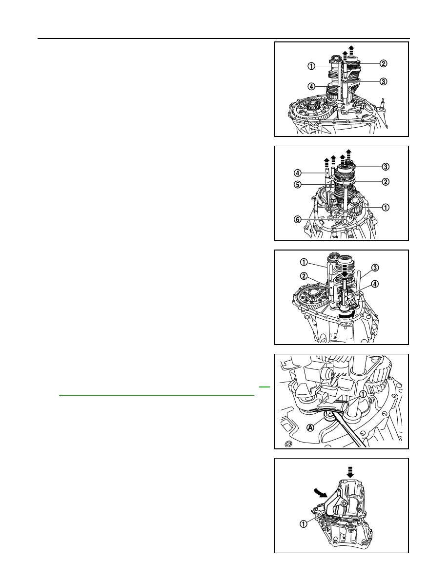
23. Install mainshaft assembly (1), as per the following procedure.
a. Pull up input shaft assembly (2) and fork rod (3).
b. Set 1st-2nd fork rod (4) to mainshaft assembly, and then install

them to clutch housing.

24. Install reverse idler shaft assembly (1), as per the following pro-

cedure.

a. Install spring washer to clutch housing.
b. Pull up input shaft assembly (2), mainshaft assembly (3), fork

rod (4), and 1st-2nd fork rod (5).

NOTE:

It is easier to pull up when shifting each fork rod to each shaft

side.

c.

Set reverse fork rod (6) to reverse idler shaft assembly, and then

install them to clutch housing.

25. Shift 1st-2nd fork rod (1), fork rod (2), and reverse fork rod (3) to

the neutral position.

26. Install selector (4) to clutch housing.

CAUTION:

Replace selector lever and selector as a set.

27. Install selector spring (1) to return bushing (A).
28. Apply recommended sealant to mounting surface of transaxle

case.

• Use Genuine Silicone RTV or an equivalent. Refer to 

GI-

22, "Recommended Chemical Products and Sealants"

.

CAUTION:

• Never allow old liquid gasket, moisture, oil, or foreign

matter to remain on mounting surface.

• Check that mounting surface is not damaged.

• Apply sealant bead continuously.

29. Install transaxle case to clutch housing while rotating shifter

lever A (1) in the direction as shown in the figure.

JPDIC0609ZZ

JPDIC0606ZZ

SCIA7782E

JPDIC0445ZZ

JPDIC0110ZZ

TRANSAXLE ASSEMBLY

TM-47

< UNIT DISASSEMBLY AND ASSEMBLY >

[6MT: RS6F94R]

C

E

F

G

H

I

J

K

L

M

A

B

TM

N

O

P

30. Install reverse idler shaft mounting bolt (

), as per the following

procedure.

a. Install seal washer to reverse idler shaft mounting bolt, and

install reverse idler shaft mounting bolt to transaxle case.

CAUTION:

Never reuse seal washer.

b. Tighten reverse idler shaft mounting bolt to the specified torque. 

31. Tighten transaxle case mounting bolts (

) to the specified

torque.

32. Install position switch (1), as per the following procedure.
a. Apply recommended sealant to threads of position switch.

• Use Genuine Silicone RTV or an equivalent. Refer to 

GI-

22, "Recommended Chemical Products and Sealants"

.

CAUTION:

Never allow old liquid gasket, moisture, oil, or foreign mat-

ter to remain on thread.

b. Install position switch to transaxle case, and tighten it to the

specified torque.

33. Install bracket (2) to transaxle case, and tighten mounting bolt to

the specified torque.

34. Install selector lever (3), as per the following procedure.
a. Install selector lever to transaxle case.

CAUTION:

Replace selector lever and selector as a set.

b. Install retaining pin to selector lever, using a pin punch.

CAUTION:

Never reuse retaining pin.

35. Install drain plug, as per the following procedure.
a. Install gasket to drain plug.

CAUTION:

Never reuse gasket.

b. Install drain plug to clutch housing, using a socket [Commercial service tool].
c. Tighten drain plug to the specified torque.
36. Install filler plug, as per the following procedure.
a. Install gasket to filler plug, and then install them to transaxle case.

CAUTION:

Never reuse gasket.

b. Tighten filler plug to the specified torque.

CAUTION:

Fill with gear oil before tighten filler plug to the specified torque.

PCIB1695E

PCIB1694E

SCIA7784E

TM-48

< UNIT DISASSEMBLY AND ASSEMBLY >

[6MT: RS6F94R]

TRANSAXLE ASSEMBLY

Inspection

INFOID:0000000012200778

INSPECTION AFTER DISASSEMBLY

Check contact surface and sliding surface for excessive wear,

uneven wear, bend, and damage. Replace if necessary.

SCIA7785E

INPUT SHAFT AND GEAR

TM-49

< UNIT DISASSEMBLY AND ASSEMBLY >

[6MT: RS6F94R]

C

E

F

G

H

I

J

K

L

M

A

B

TM

N

O

P

INPUT SHAFT AND GEAR

Exploded View

INFOID:0000000012200779

Disassembly

INFOID:0000000012200780

CAUTION:

1.

Input shaft front bearing

2.

Input shaft

3.

3rd input gear

4.

Spacer

5.

Snap ring

6.

3rd baulk ring

7.

3rd-4th coupling sleeve

8.

3rd-4th synchronizer hub

9.

Insert key

10. 4th baulk ring

11. 4th input gear

12. 5th input gear

13. 5th baulk ring

14. 5th-6th coupling sleeve

15. 5th-6th synchronizer hub

16. 6th baulk ring

17. Needle bearing 

18. 6th input gear

19. Input shaft rear bearing
A.

First step

B.

Final step

 : Apply gear oil.

 : Replace the parts as a set.

 : Always replace after every disassembly.

 : N·m (kg-m, ft-lb)

JPDIC0407GB


Content   ..  1212  1213  1214  1215   ..