Nissan Juke F15. Manual - part 1200


  Index      Nissan     Nissan Juke F15 (2015 year) - Service and Repair Manual


Search            


Content   ..  1198  1199  1200  1201   ..


Nissan Juke F15. Manual - part 1200


STR-20

< BASIC INSPECTION >

DIAGNOSIS AND REPAIR WORK FLOW

Perform the starting system test with Multitasking battery and electrical diagnostic station GR8-1200 NI. For

details and operating instructions, refer to diagnostic station Instruction Manual.
Test result

CRANKING NORMAL>>GO TO 2.

LOW VOLTAGE>>GO TO 5.

CHARGE BATTERY>>Perform  the  slow  battery charging procedure. (Initial rate of charge is 10A for 12

hours.) Perform battery test again. Refer to diagnostic station instruction manual. 

REPLACE BATTERY>>Before replacing battery, clean the battery cable clamps and battery posts. Perform

battery test again. Refer to diagnostic station instruction manual. If second test result is

“REPLACE BATTERY”, then do so. Perform battery test again to confirm repair.

2.

CRANKING CHECK

Check that the starter motor operates correctly.
Does the engine crank normally?

YES

>> GO TO 3.

NO

>> GO TO 4.

3.

ENGINE START CHECK

Check that the engine starts.
Does the engine start?

YES

>> Starter motor is OK. INSPECTION END

NO

>> Perform further diagnosis of engine mechanical or engine control system. Refer EM and EC sec-

tions. Once resolved, perform battery test again.

4.

STARTER MOTOR ACTIVATION

Check that the starter motor operates.
Does the starter motor turn?

YES

>> Check ring gear and starter motor drive pinion. Once resolved, perform battery test again.

NO

>> GO TO 7.

5.

COMPARISON BETWEEN ENGINE COOLANT AND CRANKING VOLTAGE

Compare the engine coolant temperature and the cranking voltage with the specifications.

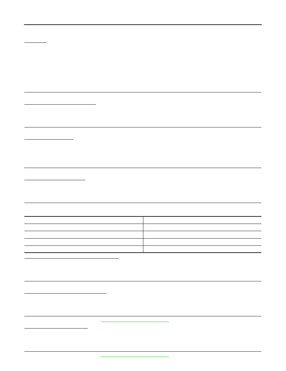
Minimum Specification of Cranking Voltage Referencing Coolant Temperature

Is the voltage less than the specified value?

YES

>> GO TO 7.

NO

>> GO TO 6.

6.

STARTER OPERATION

Check the starter operation status.
Does the starter motor turn smoothly?

YES

>> Starter motor is OK. INSPECTION END

NO

>> GO TO 7.

7.

“B” TERMINAL CIRCUIT INSPECTION

Check “B” terminal circuit. Refer to 

STR-23, "Diagnosis Procedure"

.

Is “B” terminal circuit normal?

YES

>> GO TO 8.

NO

>> Repair as needed.

8.

“S” TERMINAL CIRCUIT INSPECTION

Check “S” terminal circuit. Refer to 

STR-25, "Diagnosis Procedure"

.

Engine coolant temperature [

°C (°F)]

Voltage [V]

−30 to −20 (−22 to −4)

8.6

−19 to −10 (−2 to 14)

9.1

−9 to 0 (16 to 32)

9.5

More than 1 (More than 34)

9.9

DIAGNOSIS AND REPAIR WORK FLOW

STR-21

< BASIC INSPECTION >

C

D

E

F

G

H

I

J

K

L

M

A

STR

N

P

O

Is “S” terminal circuit normal?

YES

>> GO TO 9.

NO

>> Repair as needed.

9.

ENGINE ROTATION STATUS

Check that the engine can be rotated by hand.
Does the engine turn freely by hand?

YES

>> Replace starter motor. Refer to 

STR-28, "MR16DDT : Removal and Installation"

.

NO

>> Perform further diagnosis of engine mechanical or powertrain mechanism. Once resolved, per-

form battery test again using Multitasking battery and electrical diagnostic station GR8-1200 NI.

Refer to the diagnostic station Instruction Manual for proper testing procedures. 

Work Flow (Without GR8-1200 NI)

INFOID:0000000012201583

OVERALL SEQUENCE

DETAILED FLOW

NOTE:

If any malfunction is found, immediately disconnect the battery cable from the negative terminal.

1.

CHECK ENGINE START

Crank the engine and check that the engine starts. 
Does the engine start?

YES

>> GO TO 2.

JMBIA4454GB

STR-22

< BASIC INSPECTION >

DIAGNOSIS AND REPAIR WORK FLOW

NO

>> GO TO 3.

2.

CHECK THAT THE STARTER MOTOR STOPS

Check that the starter motor stops after starting the engine. 
Does the starter motor stop?

YES

>> INSPECTION END

NO

>> Replace starter motor. Refer to 

STR-28, "MR16DDT : Removal and Installation"

.

3.

CHECK THAT THE ENGINE TURNS WHEN CRANKING

Check that the engine turns when cranking. 
Does engine turn when cranking?

YES

>> GO TO 4.

NO

>> GO TO 5.

4.

CHECK THE ENGINE SPEED WHEN CRANKING

Check that the engine speed is not low when cranking. 
Does engine turn normally?

YES

>> Check ignition/fuel system.

NO

>> Check charge condition, corrosion and connection condition of the battery. Refer to 

PG-97, "Work

Flow"

.

5.

CHECK STARTER MOTOR ACTIVATION

Check that the starter motor runs at cranking. 
Does starter motor turn?

YES

>> Replace starter motor. Refer to 

STR-28, "MR16DDT : Removal and Installation"

.

NO

>> GO TO 6.

6.

CHECK POWER SUPPLY CIRCUIT

Check the following conditions. 

• Fuse and fusible link

• Charge condition, corrosion and connection condition of the battery. Refer to 

PG-97, "Work Flow"

.

Are these inspection results normal?

YES

>> GO TO 7.

NO

>> Repair as needed.

7.

CHECK STARTING SYSTEM WIRING

Check the following.

• “B” terminal circuit. Refer to 

STR-23, "Diagnosis Procedure"

.

• “S” terminal circuit. Refer to 

STR-25, "Diagnosis Procedure"

.

Are these inspection results normal?

YES

>> Replace starter motor. Refer to 

STR-28, "MR16DDT : Removal and Installation"

.

NO

>> Repair as needed.

B TERMINAL CIRCUIT

STR-23

< DTC/CIRCUIT DIAGNOSIS >

C

D

E

F

G

H

I

J

K

L

M

A

STR

N

P

O

DTC/CIRCUIT DIAGNOSIS

B TERMINAL CIRCUIT

Description

INFOID:0000000012201584

The “B” terminal is constantly supplied with battery power.

Diagnosis Procedure

INFOID:0000000012201585

CAUTION:

Perform diagnosis under the condition that engine cannot start by the following procedure.

1. Remove fuel pump fuse.

2. Crank or start the engine (where possible) until the fuel pressure is released.

1.

CHECK FUSIBLE LINK

Check that the following fusible link is not blown.

Is the fusible link blown?

YES

>> Replace the blown fusible link after repairing the affected circuit if a fusible link is blown.

NO

>> GO TO 2.

2.

CHECK “B” TERMINAL CIRCUIT

1. Turn ignition switch OFF.

2. Check that starter motor “B” terminal connection is clean and tight.

3. Check voltage between starter motor “B” terminal and ground.

For NISMO RS models

Except for NISMO RS models

Is the inspection result normal?

YES

>> GO TO 3.

NO

>> Check harness between battery and starter motor for open circuit.

3.

CHECK BATTERY CABLE CONNECTION STATUS (VOLTAGE DROP TEST)

1. Shift selector lever to “P” or “N” position. (CVT models)

Keep depressing clutch pedal fully. (M/T models)

2. Check voltage between battery positive terminal and starter motor “B” terminal.

For NISMO RS models

Terminal No.

Signal name

Fusible link No.

2

Battery power supply

A (225 A)

Terminals

Voltage (Approx.)

(+)

(–)

Starter motor “B” terminal

Terminal

E59

2 Ground

Battery 

voltage

Terminals

Voltage (Approx.)

(+)

(–)

Starter motor “B” terminal

Terminal

F11

2 Ground

Battery 

voltage

Terminals

Condition

Voltage (Approx.)

(+)

(–)

Starter motor

“B” terminal

Terminal

Battery positive terminal

E59

When the ignition switch 

is in START position

Less than

 0.5 V


Content   ..  1198  1199  1200  1201   ..