Content .. 1132 1133 1134 1135 ..
Nissan Juke F15. Manual - part 1134
SEC-60
< DTC/CIRCUIT DIAGNOSIS >
[WITH INTELLIGENT KEY SYSTEM]
B2198 NATS ANTENNA AMP.
Is the inspection result normal?
YES
>> Replace NATS antenna amp. Refer to
SEC-126, "Removal and Installation"
.
NO
>> GO TO 8.
8.
CHECK NATS ANTENNA AMP. OUTPUT SIGNAL CIRCUIT 2
1. Disconnect BCM connector.
2. Check continuity between NATS antenna amp. harness connector and BCM connector.
3. Check continuity between NATS antenna amp. harness connector and ground.
Is the inspection result normal?
YES
>> GO TO 9.
NO
>> Repair or replace harness.
9.
REPLACE BCM
1. Replace BCM. Refer to
BCS-94, "Removal and Installation"
.
2. Perform initialization of BCM and registration of all Intelligent Keys using CONSULT.
>> INSPECTION END
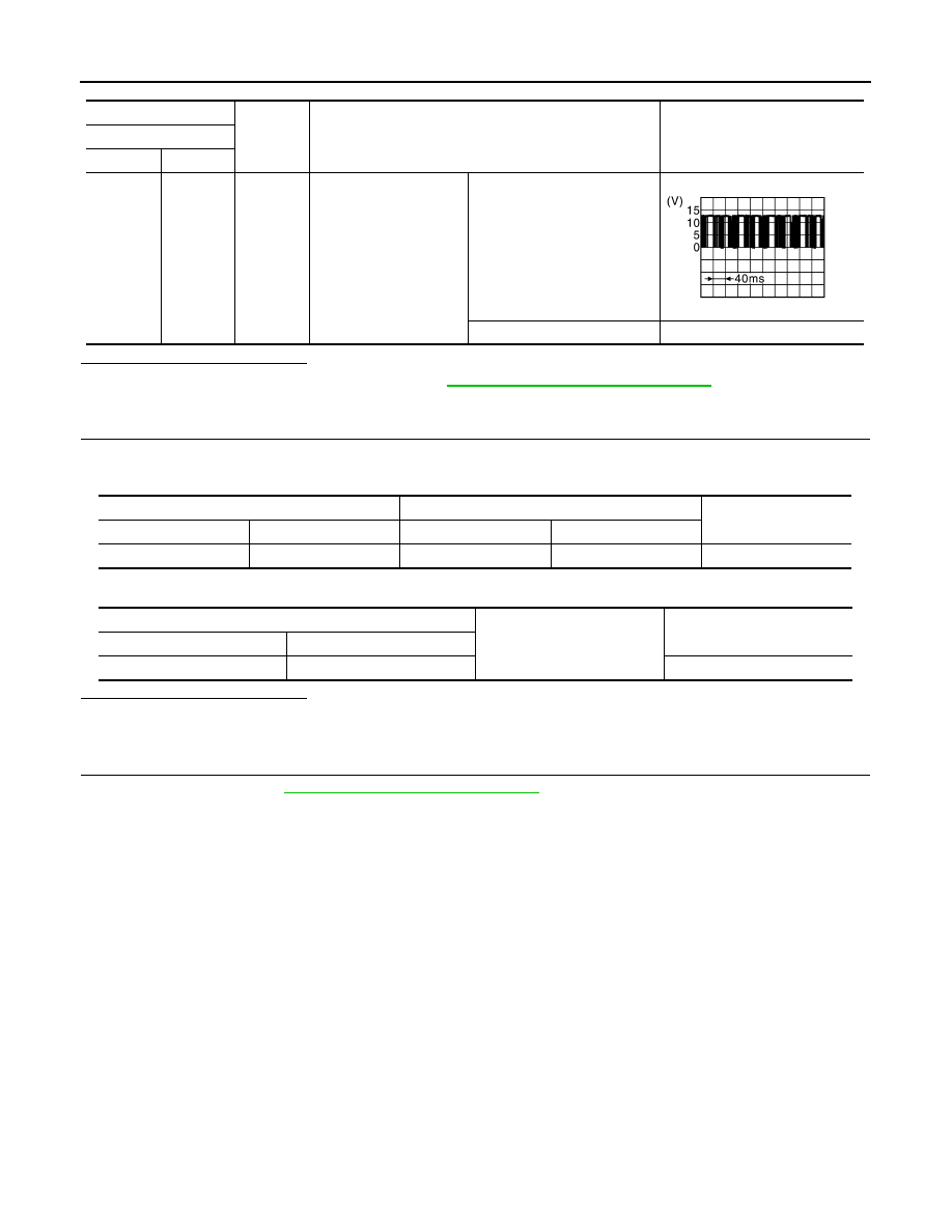
(+)
(–)
Condition
Voltage (V)
NATS antenna amp.
Connector
Terminal
M49
3
Ground
Intelligent Key: Intelligent
Key battery is removed
Brake pedal: Depressed
NOTE:
Waveform varies each time
when brake pedal is depressed
Brake pedal: Released
12
JMKIA6233JP
NATS antenna amp.
BCM
Continuity
Connector
Terminal
Connector
Terminal
M49
3
M68
25
Existed
NATS antenna amp.
Ground
Continuity
Connector
Terminal
M49
3
Not existed