Nissan Juke F15. Manual - part 108
 

  Index      Nissan     Nissan Juke F15 (2015 year) - Service and Repair Manual


Search            


Content   ..  106  107  108  109   ..


Nissan Juke F15. Manual - part 108


SYSTEM

BRC-23

< SYSTEM DESCRIPTION >

[WITH VDC]

C

D

E

G

H

I

J

K

L

M

A

B

BRC

N

O

P

• Brake fluid is supplied to the front RH brake caliper from the master cylinder through the cut valve 2 and the

ABS IN valve. Since the suction valve 2 and the ABS OUT valve is closed, the fluid does not flow into the

reservoir. The amount of brake fluid supplied to the front RH brake caliper from the master cylinder is con-

trolled according to time that the ABS IN valve is not energized (time that the ABS IN valve is open).

During pressure front LH brake caliper increases

• Brake fluid is supplied to the front LH brake caliper from the master cylinder through the cut valve 1 and the

ABS IN valve. Since the suction valve 1 and the ABS OUT valve is closed, the fluid does not flow into the

reservoir. The amount of brake fluid supplied to the front LH brake caliper from the master cylinder is con-

trolled according to time that the ABS IN valve is not energized (time that the ABS IN valve is open).

During pressure rear RH brake caliper increases

• Brake fluid is supplied to the rear RH brake caliper from the master cylinder through the cut valve 1 and the

ABS IN valve. Since the suction valve 1 and the ABS OUT valve is closed, the fluid does not flow into the

reservoir. The amount of brake fluid supplied to the rear RH brake caliper from the master cylinder is con-

trolled according to time that the ABS IN valve is not energized (time that the ABS IN valve is open).

During pressure rear LH brake caliper increases

• Brake fluid is supplied to the rear LH brake caliper from the master cylinder through the cut valve 2 and the

ABS IN valve. Since the suction valve 2 and the ABS OUT valve is closed, the fluid does not flow into the

reservoir. The amount of brake fluid supplied to the rear LH brake caliper from the master cylinder is con-

trolled according to time that the ABS IN valve is not energized (time that the ABS IN valve is open).

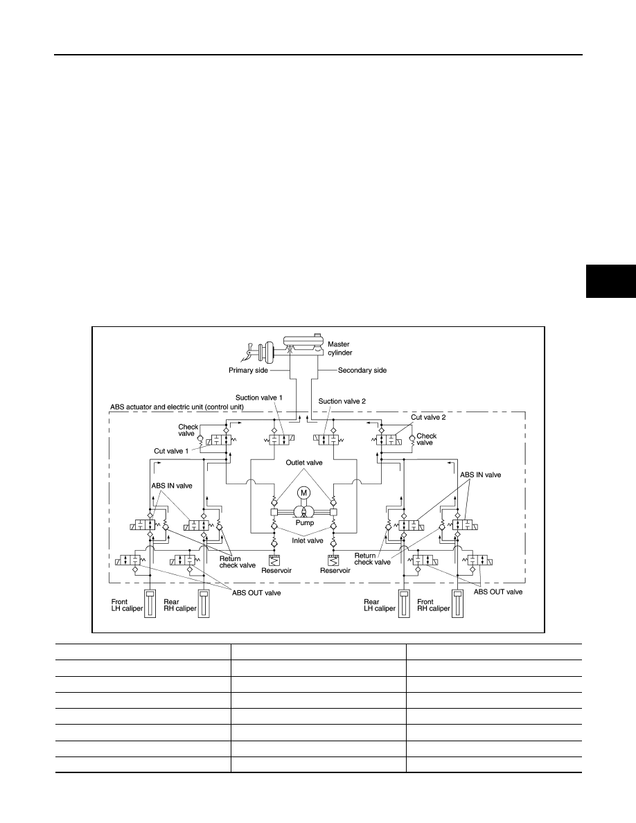
When Brake Release

JSFIA0652GB

Name

Not activated

During brake release

Cut valve 1

Power supply is not supplied (open)

Power supply is not supplied (open)

Cut valve 2

Power supply is not supplied (open)

Power supply is not supplied (open)

Suction valve 1

Power supply is not supplied (close)

Power supply is not supplied (close)

Suction valve 2

Power supply is not supplied (close)

Power supply is not supplied (close)

ABS IN valve

Power supply is not supplied (open)

Power supply is not supplied (open)

ABS OUT valve

Power supply is not supplied (close)

Power supply is not supplied (close)

Each brake caliper (fluid pressure)

Pressure decreases

BRC-24

< SYSTEM DESCRIPTION >

[WITH VDC]

SYSTEM

During front RH brake caliper release

• Brake fluid is supplied to the front RH brake caliper through the return check valve of the ABS IN valve and

the cut valve 2, and returns to the master cylinder.

During front LH brake caliper release

• Brake fluid is supplied to the front LH brake caliper through the return check valve of the ABS IN valve and

the cut valve 1, and returns to the master cylinder.

During rear RH brake caliper release

• Brake fluid is supplied to the rear RH brake caliper through the return check valve of the ABS IN valve and

the cut valve 1, and returns to the master cylinder.

During rear LH brake caliper release

• Brake fluid is supplied to the rear LH brake caliper through the return check valve of the ABS IN valve and

the cut valve 2, and returns to the master cylinder.

Component Parts and Function

CONDITION FOR TURN ON THE WARNING LAMP

Turns ON when ignition switch turns ON and turns OFF when the system is normal, for bulb check purposes.

CONDITION FOR TURN ON THE INDICATOR LAMP

Component

Function

Pump

Returns the brake fluid reserved in reservoir to master cylinder by reducing pressure.

Motor

Activates the pump according to signals from ABS actuator and electric unit (control unit).

Cut valve 1
Cut valve 2

Shuts off the ordinary brake line from master cylinder.

Suction valve 1
Suction valve 2

Supplies the brake fluid from master cylinder to the pump.

ABS IN valve

Switches the fluid pressure line to increase or hold according to signals from control unit.

ABS OUT valve

Switches the fluid pressure line to increase, hold or decrease according to signals from control unit.

Inlet valve

Brake fluid sucked from the reservoir by the pump does not backflow.

Outlet valve

Brake fluid discharged from the pump does not backflow.

Return check valve

Returns the brake fluid from brake caliper and wheel cylinder to master cylinder by bypassing orifice 
of each valve when brake is released.

Reservoir

Temporarily reserves the brake fluid drained from brake caliper, so that pressure efficiently decreas-
es when decreasing pressure of brake caliper and wheel cylinder.

Condition (status)

ABS warning lamp

Brake warning lamp

VDC warning lamp

Ignition switch OFF

OFF

OFF

OFF

For approx. 1 second after the ignition switch is turned ON

ON

ON

ON

Approx. 1 second after ignition switch is turned ON (when the sys-
tem is in normal operation)

OFF

OFF

OFF

After engine starts

OFF

OFF

OFF

When parking brake operates (parking brake switch ON)

OFF

ON

OFF

When brake fluid is less than the specified level (brake fluid level 
switch ON)

OFF

ON

OFF

VDC function is malfunctioning

OFF

OFF

ON

TCS function is malfunctioning

OFF

OFF

ON

ABS function is malfunctioning

ON

OFF

ON

EBD function is malfunctioning

ON

ON

ON

Brake limited slip differential (BLSD) function is malfunctioning

OFF

OFF

ON

VDC function is operating

OFF

OFF

Blinking

TCS function is operating

OFF

OFF

Blinking

SYSTEM

BRC-25

< SYSTEM DESCRIPTION >

[WITH VDC]

C

D

E

G

H

I

J

K

L

M

A

B

BRC

N

O

P

• Turns ON when VDC function and TCS function are switched to non-operational status (OFF) by VDC OFF

switch.

• Turns ON when ignition switch turns ON and turns OFF when the system is normal, for bulb check purposes.

Fail-safe

INFOID:0000000012199663

VDC FUNCTION, TCS FUNCTION AND BRAKE LIMITED SLIP DIFFERENTIAL (BLSD) FUNCTION

VDC warning lamp in combination meter turn ON when a malfunction occurs in system [ABS actuator and

electric unit (control unit)]. The control is suspended for VDC function, TCS function and brake limited slip dif-

ferential (BLSD) function. The vehicle status becomes the same as models without VDC function, TCS func-

tion and brake limited slip differential (BLSD) function. However, ABS function and EBD function are operated

normally.

ABS FUNCTION

ABS warning lamp and VDC warning lamp in combination meter turn ON when a malfunction occurs in system

[ABS actuator and electric unit (control unit)]. The control is suspended for VDC function, TCS function, ABS

function and brake limited slip differential (BLSD) function. The vehicle status becomes the same as models

without VDC function, TCS function, ABS function and brake limited slip differential (BLSD) function. However,

EBD function is operated normally.

NOTE:

ABS self-diagnosis sound may be heard the same as in the normal condition, because self-diagnosis is per-

formed when ignition switch turns ON and when vehicle initially starts.

EBD FUNCTION

ABS warning lamp, brake warning lamp and VDC warning lamp in combination meter turn ON when a mal-

function occurs in system [ABS actuator and electric unit (control unit)]. The control is suspended for VDC

function, TCS function, ABS function, EBD function and brake limited slip differential (BLSD) function. The

vehicle status becomes the same as models without VDC function, TCS function, ABS function, EBD function

and brake limited slip differential (BLSD) function.

Condition (status)

VDC OFF indicator lamp

Ignition switch OFF

OFF

For approx. 1 second after the ignition switch is turned ON

ON

Approx. 1 second after ignition switch is turned ON (when the sys-
tem is in normal operation)

OFF

When VDC OFF switch is ON (VDC function and TCS function are 
OFF)

ON

BRC-26

< SYSTEM DESCRIPTION >

[WITH VDC]

SYSTEM

DTC

Malfunction detected condition

Fail-safe condition

C1101

When an open circuit is detected in rear RH wheel sensor circuit.

The following functions are sus-
pended.
• VDC function
• TCS function
• ABS function
• EBD function (only when both 2 

rear wheels are malfunctioning)

• Brake limited slip differential 

(BLSD) function

C1102

When an open circuit is detected in rear LH wheel sensor circuit.

C1103

When an open circuit is detected in front RH wheel sensor circuit.

C1104

When an open circuit is detected in front LH wheel sensor circuit.

C1105

• When a short circuit is detected in rear RH wheel sensor circuit.
• When power supply voltage of rear RH wheel sensor is in following state.
- Rear RH wheel sensor power supply voltage: 7.5 V 

≥ Rear RH wheel sensor pow-

er supply voltage

- Rear RH wheel sensor power supply voltage: 16 V 

≤ Rear RH wheel sensor power 

supply voltage

• When distance between rear RH wheel sensor and rear RH wheel sensor rotor is 

large.

• When installation of rear RH wheel sensor or rear RH wheel sensor rotor is not 

normal.

C1106

• When a short circuit is detected in rear LH wheel sensor circuit.
• When power supply voltage of rear LH wheel sensor is in following state.
- Rear LH wheel sensor power supply voltage: 7.5 V 

≥ Rear LH wheel sensor power 

supply voltage

- Rear LH wheel sensor power supply voltage: 16 V 

≤ Rear LH wheel sensor power 

supply voltage

• When distance between rear LH wheel sensor and rear LH wheel sensor rotor is 

large.

• When installation of rear LH wheel sensor or rear LH wheel sensor rotor is not nor-

mal.

C1107

• When a short circuit is detected in front RH wheel sensor circuit.
• When power supply voltage of front RH wheel sensor is in following state.
- Front RH wheel sensor power supply voltage: 7.5 V 

≥ Front RH wheel sensor 

power supply voltage

- Front RH wheel sensor power supply voltage: 16 V 

≤ Front RH wheel sensor pow-

er supply voltage

• When distance between front RH wheel sensor and front RH wheel sensor rotor 

is large.

• When installation of front RH wheel sensor or front RH wheel sensor rotor is not 

normal.

C1108

• When a short circuit is detected in front LH wheel sensor circuit.
• When power supply voltage of front LH wheel sensor is in following state.
- Front LH wheel sensor power supply voltage: 7.5 V 

≥ Front LH wheel sensor pow-

er supply voltage

- Front LH wheel sensor power supply voltage: 16 V 

≤ Front LH wheel sensor power 

supply voltage

• When distance between front LH wheel sensor and front LH wheel sensor rotor is 

large.

• When installation of front LH wheel sensor or front LH wheel sensor rotor is not 

normal.

C1109

When ignition power supply voltage is in following state.
• Ignition power supply voltage: 10 V 

≥ Ignition power supply voltage.

• Ignition power supply voltage: 16 V 

≤ Ignition power supply voltage.

The following functions are sus-
pended.
• VDC function
• TCS function
• ABS function
• EBD function
• Brake limited slip differential 

(BLSD) function

C1110

When there is an internal malfunction in the ABS actuator and electric unit (control 
unit).

C1111

When a malfunction is detected in motor or motor relay.

The following functions are sus-
pended.
• VDC function
• TCS function
• ABS function
• Brake limited slip differential 

(BLSD) function


Content   ..  106  107  108  109   ..