Nissan Juke F15. Manual - part 1079


  Index      Nissan     Nissan Juke F15 (2015 year) - Service and Repair Manual


Search            


Content   ..  1077  1078  1079  1080   ..


Nissan Juke F15. Manual - part 1079


RAX-8

< REMOVAL AND INSTALLATION >

[2WD]

REAR WHEEL HUB

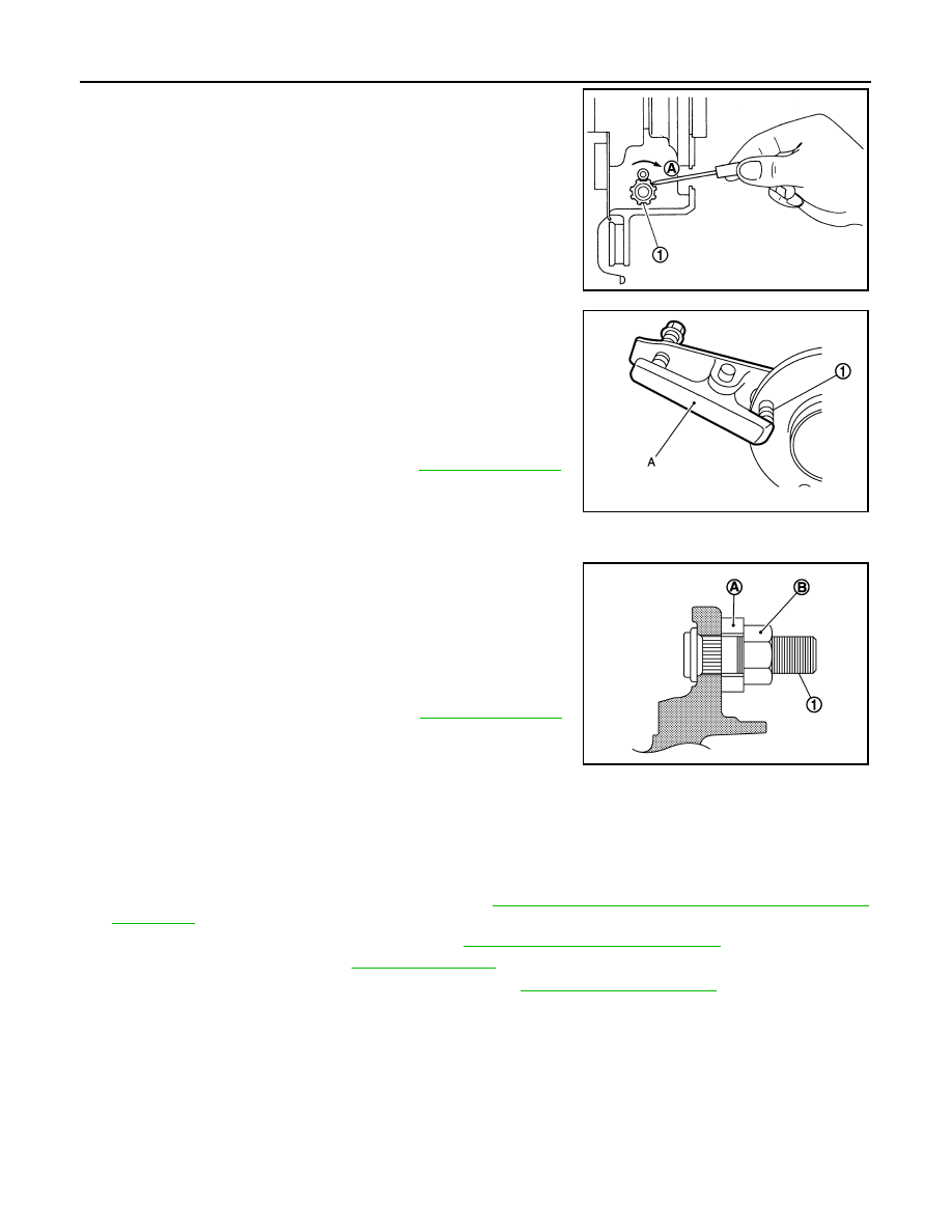
b. Using suitable tool, rotate adjuster (1) in the direction (A) to

retract and loosen brake shoe.

c.

Remove disc rotor. 

5. Remove wheel hub assembly.

CAUTION:

Never remove parking brake assembly. Protect it from fall-

ing.

6. Remove hub bolts (1) from wheel hub assembly, using the ball

joint remover (A) (commercial service tool). 

CAUTION:

• Remove hub bolt only when necessary.

• Never hammer the hub bolt to avoid impact to the wheel

hub assembly.

• Pull out the hub bolt in a direction perpendicular to the

wheel hub assembly.

7. Perform inspection after removal. Refer to 

RAX-8, "Inspection"

.

INSTALLATION

Note the following, and install in the reverse order of removal.

• Place a washer (A) as shown in the figure to install the hub bolts

(1) by using the tightening force of the nut (B).

CAUTION:

• Check that there is no clearance between wheel hub assem-

bly and hub bolt.

• Never reuse hub bolt.

• Align the matching marks that have been made during removal

when reusing the disc rotor.

• Perform inspection after installation. Refer to 

RAX-8, "Inspection"

.

Inspection

INFOID:0000000012196552

INSPECTION AFTER REMOVAL

Check the wheel hub assembly for wear, cracks, and damage. Replace if necessary.

INSPECTION AFTER INSTALLATION

1. Check wheel sensor harness for proper connection. 

BRC-150, "REAR WHEEL SENSOR : Removal and

Installation"

.

2. Adjust parking brake operation (stroke). Refer to 

PB-11, "Inspection and Adjustment"

.

3. Check wheel alignment. Refer to 

RSU-7, "Inspection"

.

4. Adjust neutral position of steering angle sensor. Refer to 

BRC-63, "Work Procedure"

.

JPDIG0204ZZ

JPDIF0299ZZ

JPDIF0300ZZ

SERVICE DATA AND SPECIFICATIONS (SDS)

RAX-9

< SERVICE DATA AND SPECIFICATIONS (SDS) 

[2WD]

C

E

F

G

H

I

J

K

L

M

A

B

RAX

N

O

P

SERVICE DATA AND SPECIFICATIONS (SDS)

SERVICE DATA AND SPECIFICATIONS (SDS)

Wheel Bearing

INFOID:0000000012196553

Item

Standard

Axial end play

0.05 mm (0.002 in) or less

RAX-10

< PRECAUTION >

[AWD]

PRECAUTIONS

PRECAUTION

PRECAUTIONS

Precautions for Drive Shaft

INFOID:0000000012196554

• Observe the following precautions when disassembling and assembling drive shaft.

- Never disassemble joint sub-assembly because it is non-overhaul parts.

- Perform work in a location which is as dust-free as possible.

- Clean the parts, before disassembling and assembling.

- Prevent the entry of foreign objects during disassembly of the service location.

- Reassemble disassembled parts carefully in the correct order. If work is interrupted, a clean cover must be

placed over parts.

- Use paper waste. Fabric shop cloths must not be used because of the danger of lint adhering to parts.

- Clean disassembled parts (except for rubber parts) with kerosene which shall be removed by blowing with

air or wiping with paper waste.

Precautions for Removing Battery Terminal

INFOID:0000000012833628

When disconnecting the battery terminal, pay attention to the following.

• Always use a 12V battery as power source.

• Never disconnect battery terminal while engine is running.

• When removing the 12V battery terminal, turn OFF the ignition

switch and wait at least 30 seconds.

• For vehicles with the engine listed below, remove the battery termi-

nal after a lapse of the specified time:

NOTE:

ECU may be active for several tens of seconds after the ignition switch is turned OFF. If the battery terminal

is removed before ECU stops, then a DTC detection error or ECU data corruption may occur.

• After high-load driving, if the vehicle is equipped with the V9X engine, turn the ignition switch OFF and wait

for at least 15 minutes to remove the battery terminal.

NOTE:

• Turbocharger cooling pump may operate in a few minutes after the ignition switch is turned OFF.

• Example of high-load driving

- Driving for 30 minutes or more at 140 km/h (86 MPH) or more.

- Driving for 30 minutes or more on a steep slope.

• For vehicles with the 2-batteries, be sure to connect the main battery and the sub battery before turning ON

the ignition switch.

NOTE:

If the ignition switch is turned ON with any one of the terminals of main battery and sub battery discon-

nected, then DTC may be detected.

• After installing the 12V battery, always check "Self Diagnosis Result" of all ECUs and erase DTC.

NOTE:

The removal of 12V battery may cause a DTC detection error.

D4D engine

: 20 minutes

YS23DDT

: 4 minutes

HRA2DDT

: 12 minutes

YS23DDTT

: 4 minutes

K9K engine

: 4 minutes

ZD30DDTi

: 60 seconds

M9R engine

: 4 minutes

ZD30DDTT

: 60 seconds

R9M engine

: 4 minutes

V9X engine

: 4 minutes

YD25DDTi

: 2 minutes

SEF289H

PREPARATION

RAX-11

< PREPARATION >

[AWD]

C

E

F

G

H

I

J

K

L

M

A

B

RAX

N

O

P

PREPARATION

PREPARATION

Special Service Tool

INFOID:0000000012196556

The actual shapes of Kent-Moore tools may differ from those of special service tools illustrated here.

Commercial Service Tools

INFOID:0000000012196557

Tool number 
(Kent-More No.)
Tool name

Description

KV38100500
(

)

Drift
a: 80 mm (3.15 in) dia.
b: 60 mm (2.36 in) dia.

Installing sensor rotor

KV40101840
(

)

Color
a: 67 mm (2.64 in) dia.
b: 85 mm (3.35 in) dia.

Installing sensor rotor

KV40107300
(

)

Boot band crimping tool

Installing boot band

KV38107900
(

)

Protector
a: 32 mm (1.26 in) dia.

Installing drive shaft

ZZA0701D

ZZA1113D

ZZA1229D

PDIA1183J


Content   ..  1077  1078  1079  1080   ..