Nissan Juke F15. Manual - part 1064


  Index      Nissan     Nissan Juke F15 (2015 year) - Service and Repair Manual


Search            


Content   ..  1062  1063  1064  1065   ..


Nissan Juke F15. Manual - part 1064


SYSTEM

PWC-9

< SYSTEM DESCRIPTION >

C

D

E

F

G

H

I

J

L

M

A

B

PWC

N

O

P

SYSTEM

POWER WINDOW SYSTEM
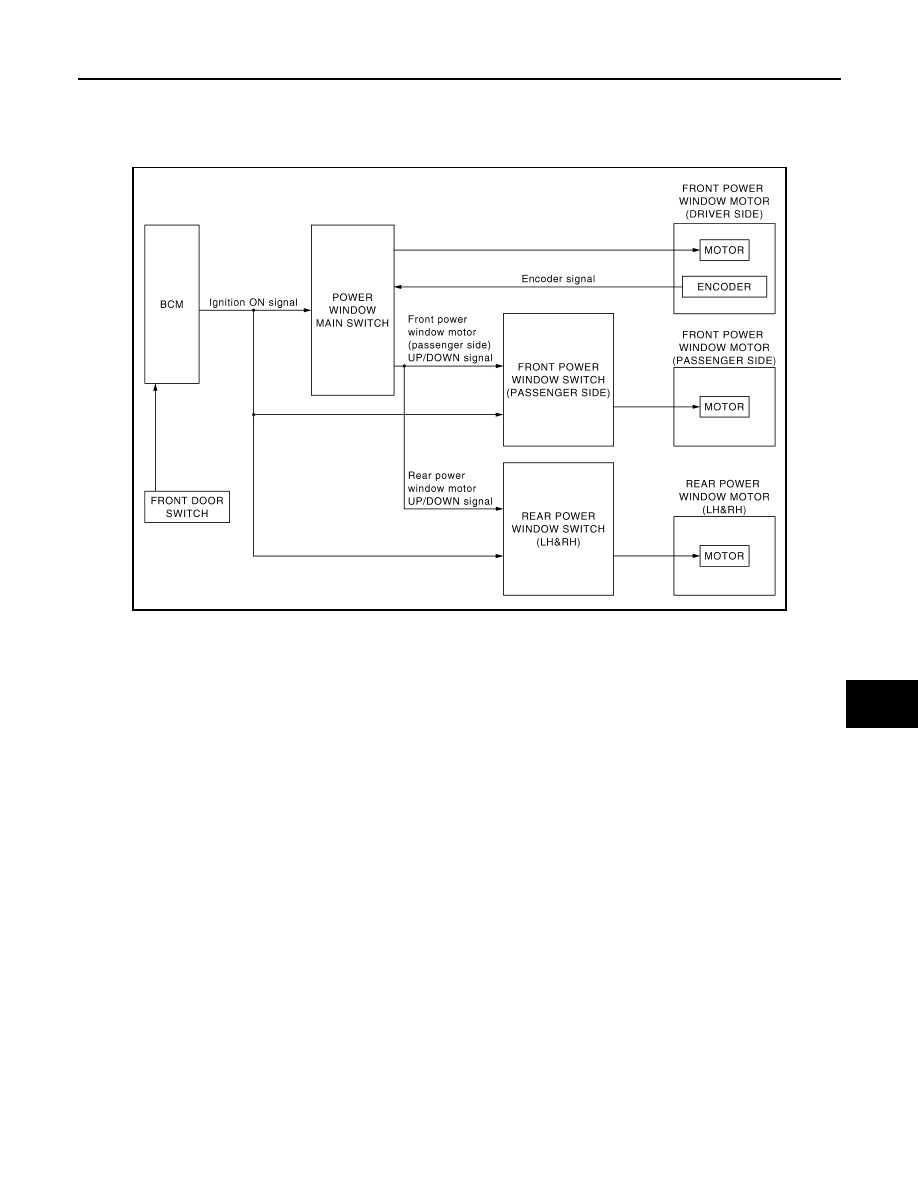
POWER WINDOW SYSTEM : System Diagram

INFOID:0000000012196897

POWER WINDOW SYSTEM : System Description

INFOID:0000000012196898

• Power window system is activated by power window switch when ignition switch turns ON, or during the

retained power operation after ignition switch turns OFF.

• Power window main switch opens/closes all door glass.

• Front and rear power window switch opens/closes the corresponding door glass.

• AUTO UP/DOWN operation can be performed when power window main switch turns to AUTO.

• Power window lock switch can lock all power windows other than driver seat.

• If door glass receives resistance that is the specified value or more while power window of driver seat is in

AUTO-UP operation, power window of driver seat operates in the reverse direction.

POWER WINDOW AUTO-OPERATION (FRONT DRIVER SIDE)

• AUTO UP/DOWN operation can be performed when power window main switch turns to AUTO.

• Encoder continues detecting the movement of power window motor and transmits to power window switch

as the encoder signal while power window motor is operating.

• Power window switch reads the changes of encoder signal and stops AUTO operation when door glass is at

fully opened/closed position.

• Power window motor is operable in case encoder is malfunctioning.

RETAINED POWER OPERATION

Retained power operation is an additional power supply function that enables power window system to oper-

ate for 45 seconds even when ignition switch is turned OFF.

Retained Power Cancel Conditions

• Front door CLOSE (door switch OFF) 

→ OPEN (door switch ON).

• When ignition switch is ON again.

• When timer time passes (45 seconds).

POWER WINDOW LOCK

JMKIB3472GB

PWC-10

< SYSTEM DESCRIPTION >

SYSTEM

Ground circuit inside power window main switch shuts off when power window lock switch is ON. This inhibits

each power window switch operation except the power window main switch.

ANTI-PINCH SYSTEM (FRONT DRIVER SIDE)

• Pinch foreign material in the door glass during AUTO-UP operation, and it is the anti-pinch function that low-

ers the door glass 150 mm (5.9 in) when detected.

• Encoder continues detecting the movement of front power window motor (driver side) and transmits to

power window main switch as the encoder signal while front power window motor (driver side) is operating.

• Resistance is applied to the front power window motor (driver side) rotation that changes the frequency of

encoder signal if foreign material is trapped in the door glass.

• Power window main switch controls to lower the window glass for 150 mm (5.9 in) after it detects encoder

signal frequency change.

Operation Condition

When front door glass (driver side) AUTO-UP operation is performed (anti-pinch function does not operate just

before the door glass closes and is fully closed).

NOTE:

Depending on environment and driving conditions, if a similar impact or load is applied to the door glass, it

may lower.

Fail-safe

INFOID:0000000012196899

FAIL-SAFE CONTROL

Switches to fail-safe control when malfunction is detected in encoder signal that detects up/down speed and

direction of door glass. Switches to fail-safe control when error beyond regulation value is detected between

the fully closed position and the actual position of the glass.

It changes to condition before initialization and the following functions do not operate when switched to fail-

safe control.

• Auto-up operation

• Anti-pinch function

Perform initial operation to recover when switched to fail-safe mode. However, it switches back to fail-safe

control when malfunction is found in power window main switch or front power window motor (driver side).

Error

Error condition

Pulse sensor malfunction

When only one side of pulse signal is being detected for more than the specified value.

Both pulse sensors mal-
function

When both pulse signals have not been detected for more than the specified value during glass 
open/close operation.

Pulse direction malfunc-
tion

When the pulse signal that is detected during glass open/close operation detects the opposite con-
dition of power window motor operating direction.

Glass recognition position 
malfunction 1

When it detects the error between glass fully closed position in power window switch memory and 
actual fully closed position during glass open/close operation is more than the specified value.

Glass recognition position 
malfunction 2

When it detects pulse count more than the value of glass full stroke during glass open/close opera-
tion.

DIAGNOSIS SYSTEM (BCM)

PWC-11

< SYSTEM DESCRIPTION >

C

D

E

F

G

H

I

J

L

M

A

B

PWC

N

O

P

DIAGNOSIS SYSTEM (BCM)

COMMON ITEM
COMMON ITEM : CONSULT Function (BCM - COMMON ITEM)

INFOID:0000000012196900

APPLICATION ITEM

CONSULT performs the following functions via CAN communication with BCM.

SYSTEM APPLICATION

BCM can perform the following functions for each system.

NOTE:

It can perform the diagnosis modes except the following for all sub system selection items.

×: Applicable item

NOTE:
*: For models with automatic A/C, this diagnosis mode is not used.

FREEZE FRAME DATA (FFD)

The BCM records the following vehicle condition at the time a particular DTC is detected, and displays on

CONSULT.

Diagnosis mode

Function Description

Work Support

Changes the setting for each system function.

Self Diagnostic Result

Displays the diagnosis results judged by BCM.

CAN Diag Support Monitor

Monitors the reception status of CAN communication viewed from BCM.

Data Monitor

The BCM input/output signals are displayed.

Active Test

The signals used to activate each device are forcibly supplied from BCM.

Ecu Identification

The BCM part number is displayed.

Configuration

• Read and save the vehicle specification.
• Write the vehicle specification when replacing BCM.

System

Sub system selection item

Diagnosis mode

Work Support

Data Monitor

Active Test

Door lock

DOOR LOCK

×

×

×

Rear window defogger

REAR DEFOGGER

×

×

Warning chime

BUZZER

×

×

Interior room lamp timer

INT LAMP

×

×

×

Exterior lamp

HEAD LAMP

×

×

×

Wiper and washer

WIPER

×

×

×

Turn signal and hazard warning lamps

FLASHER

×

×

×

Air conditioning system

AIR CONDITONER

×

×*

• Intelligent Key system
• Engine start system

INTELLIGENT KEY

×

×

×

Combination switch

COMB SW

×

Body control system

BCM

×

NVIS - NATS

IMMU

×

×

×

Interior room lamp battery saver

BATTERY SAVER

×

×

×

Back door open

TRUNK

×

Theft warning alarm

THEFT ALM

×

×

×

RAP

RETAINED PWR

×

Signal buffer system

SIGNAL BUFFER

×

×

TPMS

AIR PRESSURE MONITOR

×

×

×

PWC-12

< SYSTEM DESCRIPTION >

DIAGNOSIS SYSTEM (BCM)

NOTE:
*: Power position shifts to “LOCK” from “OFF”, when ignition switch is in the OFF position, selector lever is in the P position (A/T models
and CVT models), and any of the following conditions are met.
• Closing door
• Opening door
• Door is locked using door request switch
• Door is locked using Intelligent Key
The power position shifts to “ACC” when the push-button ignition switch (push switch) is pushed at “LOCK”.

RETAIND PWR
RETAIND PWR : CONSULT Function (BCM - RETAINED PWR)

INFOID:0000000012196901

DATA MONITOR

NOTE:

The following table includes information (items) inapplicable to this vehicle. For information (items) applicable

to this vehicle, refer to CONSULT display items.

CONSULT screen item

Indication/Unit

Description

Vehicle Speed

km/h

Vehicle speed of the moment a particular DTC is detected

Odo/Trip Meter

km

Total mileage (Odometer value) of the moment a particular DTC is detected

Vehicle Condition

SLEEP>LOCK

Power position status of 
the moment a particular 
DTC is detected

While turning BCM status from low power consumption mode to 
normal mode (Power position is “LOCK”*.)

SLEEP>OFF

While turning BCM status from low power consumption mode to 
normal mode (Power position is “OFF”.)

LOCK>ACC

While turning power position from “LOCK”* *to “ACC”

ACC>ON

While turning power position from “ACC” to “IGN”

RUN>ACC

While turning power position from “RUN” to “ACC” (Vehicle is 
stopping and selector lever is except P position.)

CRANK>RUN

While turning power position from “CRANKING” to “RUN” (From 
cranking up the engine to run it)

RUN>URGENT

While turning power position from “RUN“ to “ACC” (Emergency 
stop operation)

ACC>OFF

While turning power position from “ACC” to “OFF”

OFF>LOCK

While turning power position from “OFF” to “LOCK”*

OFF>ACC

While turning power position from “OFF” to “ACC”

ON>CRANK

While turning power position from “IGN” to “CRANKING”

OFF>SLEEP

While turning BCM status from normal mode (Power position is 
“OFF”.) to low power consumption mode

LOCK>SLEEP

While turning BCM status from normal mode (Power position is 
“LOCK”*.) to low power consumption mode

LOCK

Power position is “LOCK”*

OFF

Power position is “OFF” (Ignition switch OFF)

ACC

Power position is “ACC” (Ignition switch ACC)

ON

Power position is “IGN” (Ignition switch ON with engine stopped)

ENGINE RUN

Power position is “RUN” (Ignition switch ON with engine running)

CRANKING

Power position is “CRANKING” (At engine cranking)

IGN Counter

0 - 39

The number of times that ignition switch is turned ON after DTC is detected
• The number is 0 when a malfunction is detected now.
• The number increases like 1 

→ 2 → 3...38 → 39 after returning to the normal condition 

whenever ignition switch OFF 

→ ON.

• The number is fixed to 39 until the self-diagnosis results are erased if it is over 39.


Content   ..  1062  1063  1064  1065   ..