Nissan Juke F15. Manual - part 1024


  Index      Nissan     Nissan Juke F15 (2015 year) - Service and Repair Manual


Search            


Content   ..  1022  1023  1024  1025   ..


Nissan Juke F15. Manual - part 1024


PCS-40

< PRECAUTION >

[POWER DISTRIBUTION SYSTEM]

PRECAUTIONS

• Never use electrical test equipment on any circuit related to the SRS unless instructed to in this Ser-

vice Manual. SRS wiring harnesses can be identified by yellow and/or orange harnesses or harness

connectors.

PRECAUTIONS WHEN USING POWER TOOLS (AIR OR ELECTRIC) AND HAMMERS

WARNING:

Always observe the following items for preventing accidental activation.

• When working near the Air Bag Diagnosis Sensor Unit or other Air Bag System sensors with the

ignition ON or engine running, never use air or electric power tools or strike near the sensor(s) with

a hammer. Heavy vibration could activate the sensor(s) and deploy the air bag(s), possibly causing

serious injury.

• When using air or electric power tools or hammers, always switch the ignition OFF, disconnect the

battery or batteries, and wait at least 3 minutes before performing any service.

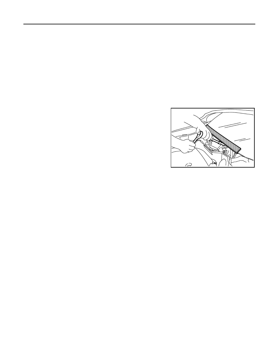
Precaution for Procedure without Cowl Top Cover

INFOID:0000000012197178

When performing the procedure after removing cowl top cover, cover

the lower end of windshield with urethane, etc to prevent damage to

windshield.

PIIB3706J

PCS

COMPONENT PARTS

PCS-41

< SYSTEM DESCRIPTION >

[POWER DISTRIBUTION SYSTEM]

C

D

E

F

G

H

I

J

K

L

B

A

O

P

N

SYSTEM DESCRIPTION

COMPONENT PARTS

Component Parts Location

INFOID:0000000012197179

Component Description

INFOID:0000000012197180

BCM

INFOID:0000000012197181

BCM controls the various electrical components and simultaneously supplies power according to the power

supply position.

BCM checks the power supply position internally.

Ignition Relay

INFOID:0000000012197182

BCM turns ON the following relays to supply ignition power supply or ignition switch ON signal to each ECU

when the ignition switch is turned ON.

• Ignition relay (fuse block)

• Ignition relay (IPDM E/R)

• Blower relay

1.

Push-button ignition switch

2.

IPDM E/R
Refer to 

PCS-5, "Component Parts 

Location"

3.

Transmission range switch
Refer to 

TM-156, "CVT CONTROL 

SYSTEM : Component Parts Loca-
tion"

4.

Stop lamp switch
Refer to 

BRC-9, "Component Parts 

Location"

5.

Clutch interlock switch
Refer to 

STR-5, "Component Parts 

Location"

6.

BCM
Refer to 

BCS-5, "BODY CONTROL 

SYSTEM : Component Parts Loca-
tion"

JMMIA0638ZZ

BCM

Reference

BCM

PCS-41

Ignition relay

PCS-41

Accessory relay

PCS-42

Blower relay

PCS-42

Push-button ignition switch

PCS-42

Stop lamp switch

PCS-42

Transmission range switch

PCS-42

Clutch interlock switch

PCS-42

PCS-42

< SYSTEM DESCRIPTION >

[POWER DISTRIBUTION SYSTEM]

COMPONENT PARTS

BCM compares following status comparing.

• Ignition relay (fuse block) control signal, and power supply position judged by BCM

• Ignition relay (IPDM E/R) control request, and Ignition relay (IPDM E/R) status

Accessory Relay

INFOID:0000000012197183

BCM turns ON the accessory relays to supply accessory power supply or ignition switch ACC signal to each

ECU when the ignition switch is turned ACC or ON.

BCM compares status of accessory relay control signal, and power supply position judged by BCM.

Blower Relay

INFOID:0000000012197184

BCM turns ON the following relays to supply ignition power supply or ignition switch ON signal to each ECU

when the ignition switch is turned ON.

• Ignition relay (fuse block)

• Ignition relay (IPDM E/R)

• Blower relay

BCM compares status of blower relay control signal, and power supply position judged by BCM.

Push-Button Ignition Switch

INFOID:0000000012197185

BCM transmits the change in the power supply position with the push-button ignition switch to IPDM E/R via

CAN communication line. IPDM E/R transmits the power supply position status via CAN communication line to

BCM.

Stop Lamp Switch

INFOID:0000000012197186

Stop lamp switch detects that brake pedal is depressed, and then transmits the signal to BCM.

Transmission Range Switch

INFOID:0000000012197187

Transmission range switch is integrated in CVT assembly, and detects the CVT shift selector position.

Transmission range switch detects selector lever position (P/N position), and transmits the P/N position signal

to BCM.

Clutch Interlock Switch

INFOID:0000000012197188

Clutch interlock switch detects that clutch pedal is depressed, and transmits ON/OFF signal to BCM.

PCS

SYSTEM

PCS-43

< SYSTEM DESCRIPTION >

[POWER DISTRIBUTION SYSTEM]

C

D

E

F

G

H

I

J

K

L

B

A

O

P

N

SYSTEM

POWER DISTRIBUTION SYSTEM
POWER DISTRIBUTION SYSTEM : System Diagram

INFOID:0000000012197189

POWER DISTRIBUTION SYSTEM : System Description

INFOID:0000000012197190

SYSTEM DESCRIPTION

• PDS (POWER DISTRIBUTION SYSTEM) is the system that BCM controls with the operation of the push-

button ignition switch and performs the power distribution to each power circuit. This system is used instead

of the mechanical power supply changing mechanism with the operation of the conventional key cylinder.

• The push-button ignition switch can be operated when Intelligent Key is in the following condition. Refer to

Engine Start Function for details.

- Intelligent Key is in the detection area of the inside key antenna.

- Intelligent Key backside is contacted to push-button ignition switch.

• The push-button ignition switch operation is input to BCM as a signal. BCM changes the power supply posi-

tion according to the status and operates the following relays to supply power to each power circuit.

- Ignition relay (IPDM E/R)

- Ignition relay (fuse block)

- ACC relay

- Blower relay

NOTE:

The push-button ignition switch operation changes due to the conditions of brake pedal, selector lever and

vehicle speed.

• The power supply position can be confirmed with the lighting of ACC/ON indicator in the push-button ignition

switch.

IGNITION BATTERY SAVER SYSTEM

Ignition Position [ON]

When all the following conditions are met for 10 minutes, the battery saver system will cut off the power supply

(ignition switch position ON 

→ OFF) to prevent battery discharge.

Ignition Position [ACC]

When all the following conditions are met for 30 minutes, the battery saver system will cut off the power supply

(ignition switch position ACC 

→ OFF) to prevent battery discharge.

• Ignition switch is in the ACC position

• Turn signal lamp is not in operation

• Selector lever is in the P position

Reset Condition of Ignition Battery Saver System

If any of the following conditions are met the battery saver system is released.

• Ignition switch is not in the ACC/ON position.

JMMIA0639GB


Content   ..  1022  1023  1024  1025   ..