Nissan Juke F15. Manual - part 1022


  Index      Nissan     Nissan Juke F15 (2015 year) - Service and Repair Manual


Search            


Content   ..  1020  1021  1022  1023   ..


Nissan Juke F15. Manual - part 1022


PCS-32

< DTC/CIRCUIT DIAGNOSIS >

[IPDM E/R]

B2098 IGNITION RELAY ON STUCK

B2098 IGNITION RELAY ON STUCK

Description

INFOID:0000000012197167

• IPDM E/R operates the ignition relay when it receives an ignition switch ON signal from BCM via CAN com-

munication.

• Turn the ignition relay OFF by pressing the push-button ignition switch once when the vehicle speed is 4 km/

h (2.5 MPH) or less.

• Turn the ignition relay OFF with the following operation when the vehicle speed is more than 4 km/h (2.5

MPH) or when an abnormal condition occurs in CAN communication from the combination meter (Emer-

gency OFF)

- Press and hold the push-button ignition switch for 2 seconds or more.

- Press the push-button ignition switch 3 times within 1.5 seconds.

NOTE:

The ignition relay does not turn ON for 3 seconds after emergency OFF even if the push-button ignition switch

is pressed.

DTC Logic

INFOID:0000000012197168

DTC DETECTION LOGIC

1.

PERFORM DTC CONFIRMATION PROCEDURE

1. Turn ignition switch ON.

2. Check DTC in “Self Diagnostic Result” mode of “IPDM E/R” using CONSULT.
Is DTC detected?

YES

>> Refer to 

PCS-32, "Diagnosis Procedure"

.

NO

>> INSPECTION END.

Diagnosis Procedure

INFOID:0000000012197169

1.

CHECK SELF DIAGNOSTIC RESULT

Check DTC using CONSULT.
What is the display history of DTC “B2098”?

“CRNT”>> GO TO 2.

“PAST” >> GO TO 5.

2.

CHECK IGNITION RELAY CONTROL CIRCUIT VOLTAGE 1

1. Turn ignition switch ON

2. Check voltage between IPDM E/R harness connector and ground.

Is the inspection result normal?

YES

>> GO TO 4.

NO

>> GO TO 3.

3.

CHECK IGNITION RELAY CONTROL CIRCUIT VOLTAGE 2

1. Disconnect IPDM E/R connector.

2. Turn ignition switch ON
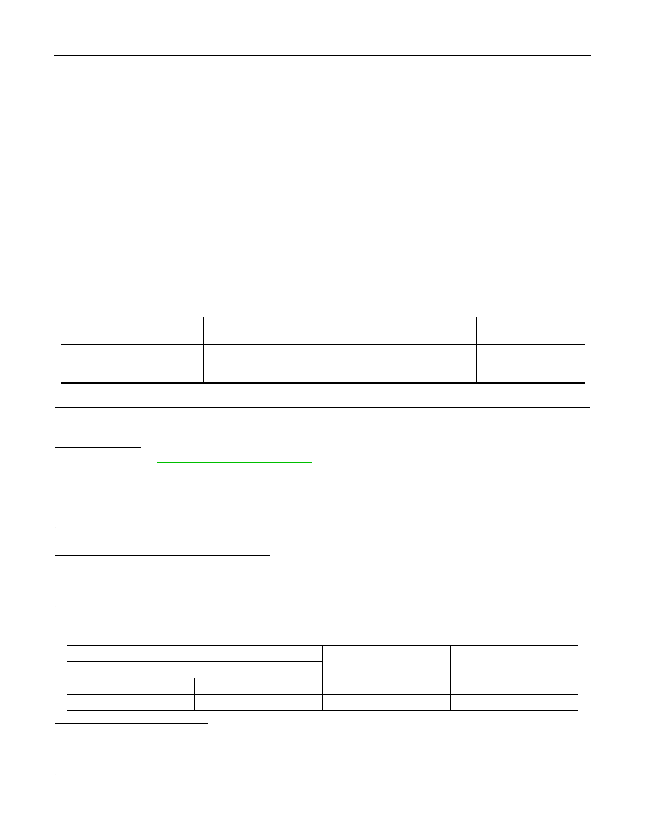
DTC

CONSULT display 

description

DTC Detection Condition

Possible causes

B2098

IGN RELAY ON 
CIRC

The ignition relay ON is detected for 1 second at ignition switch OFF
(CPU monitors the status at the contact and excitation coil circuits 
of the ignition relay inside it)

Ignition relay malfunction

(+)

(–)

Voltage

(Approx.)

IPDM E/R

Connector

Terminal

E17

68

Ground

0 V

PCS

B2098 IGNITION RELAY ON STUCK

PCS-33

< DTC/CIRCUIT DIAGNOSIS >

[IPDM E/R]

C

D

E

F

G

H

I

J

K

L

B

A

O

P

N

3. Check voltage between IPDM E/R harness connector and ground.

Is the inspection result normal?

YES

>> Replace IPDM E/R. Refer to 

PCS-37, "Removal and Installation"

.

NO

>> Check the harness of the ignition relay control circuit for a short to power.

4.

CHECK IGNITION RELAY CONTROL CIRCUIT

1. Disconnect IPDM E/R connector.

2. Check continuity between IPDM E/R harness connector and ground.

Is the inspection result normal?

YES

>> Perform the diagnosis procedure for DTC B26F2. Refer to 

PCS-75, "DTC Logic"

.

NO

>> Repair or replace harness.

5.

CHECK INTERMITTENT INCIDENT

Refer to 

GI-45, "Intermittent Incident"

.

>> INSPECTION END

(+)

(–)

Voltage

(Approx.)

IPDM E/R

Connector

Terminal

E17

68

Ground

0 V

IPDM E/R

Ground

Continuity

Connector

Terminal

E17

68

Not existed

PCS-34

< DTC/CIRCUIT DIAGNOSIS >

[IPDM E/R]

B2099 IGNITION RELAY OFF STUCK

B2099 IGNITION RELAY OFF STUCK

Description

INFOID:0000000012197170

• IPDM E/R operates the ignition relay when it receives an ignition switch ON signal from BCM via CAN com-

munication.

• Turn the ignition relay OFF by pressing the push-button ignition switch once when the vehicle speed is 4 km/

h (2.5 MPH) or less.

• Turn the ignition relay OFF with the following operation when the vehicle speed is more than 4 km/h (2.5

MPH) or when an abnormal condition occurs in CAN communication from the combination meter (Emer-

gency OFF)

- Press and hold the push-button ignition switch for 2 seconds or more.

- Press the push-button ignition switch 3 times within 1.5 seconds.

NOTE:

The ignition relay does not turn ON for 3 seconds after emergency OFF even if the push-button ignition switch

is pressed.

DTC Logic

INFOID:0000000012197171

DTC DETECTION LOGIC

NOTE:
When IPDM E/R power supply voltage is low (Approx. 7 - 8 V for about 1 second), the “DTC: B2099” may be detected.

1.

PERFORM DTC CONFIRMATION PROCEDURE

1. Turn ignition switch ON.

2. Check DTC in “Self Diagnostic Result” mode of “IPDM E/R” using CONSULT.
Is DTC detected?

YES

>> Refer to 

PCS-34, "Diagnosis Procedure"

.

NO

>> INSPECTION END.

Diagnosis Procedure

INFOID:0000000012197172

1.

CHECK FUSE

Check that all of the fuses installed on the downstream of the contact point side circuit of the ignition relay in

IPDM E/R are not blown.
Is the inspection result normal?

YES

>> GO TO 2.

NO

>> Replace the blown fuse after replacing the affected circuit if a fuse is blown.

2.

CHECK IGNITION RELAY CONTROL CIRCUIT VOLTAGE

1. Turn ignition switch ON

2. Check voltage between IPDM E/R harness connector and ground.

Is the inspection result normal?

YES

>> Replace IPDM E/R. Refer to 

PCS-37, "Removal and Installation"

.

NO

>> GO TO 3.

DTC

CONSULT display 

description

DTC Detection Condition

Possible causes

B2099

IGN RELAY OFF 
CIRC

The ignition relay OFF is detected for 1 second at ignition switch ON
(CPU monitors the status at the contact and excitation coil circuits of 
the ignition relay inside it)

Ignition relay malfunction

(+)

(–)

Voltage

(Approx)

IPDM E/R

Connector

Terminal

E17

68

Ground

0 V

PCS

B2099 IGNITION RELAY OFF STUCK

PCS-35

< DTC/CIRCUIT DIAGNOSIS >

[IPDM E/R]

C

D

E

F

G

H

I

J

K

L

B

A

O

P

N

3.

CHECK BATTERY VOLTAGE

Check battery voltage.
Which is the measurement result?

More than 12.4 V>>GO TO 4.

Less than 12.4 V>>Perform battery inspection. Refer to 

PG-97, "How to Handle Battery"

.

4.

CHECK INTERMITTENT INCIDENT

Refer to 

GI-45, "Intermittent Incident"

.

>> INSPECTION END


Content   ..  1020  1021  1022  1023   ..