Content .. 1000 1001 1002 1003 ..
Nissan Juke F15. Manual - part 1002
MWI-30
< ECU DIAGNOSIS INFORMATION >
COMBINATION METER
Terminal No.
(Wire color)
Description
Condition
Value
(Approx.)
+
–
Signal name
Input/
Output
1
(L)
—
CAN-H
—
—
—
—
2
(P)
—
CAN-L
—
—
—
—
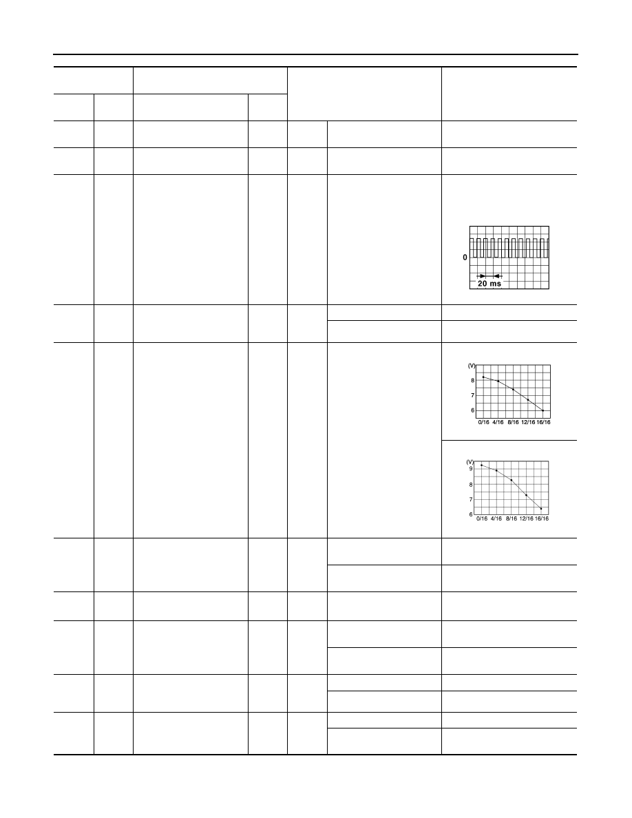
4
(Y)
Ground
Vehicle speed signal
(8-pulse)
Output
Ignition
switch
ON
Speedometer operated
[When vehicle speed is ap-
prox. 40 km/h (25 MPH)]
NOTE:
The maximum voltage varies de-
pending on the specification
(destination unit).
5
(G)
Ground
Paddle shifter up switch
signal
Input
Ignition
switch
ON
Paddle shifter up operated
0 V
Other than the above
12 V
6
(BR)
Ground Fuel level sensor signal
Input
Ignition
switch
ON
—
2WD
AWD
7
(R)
Ground
Air bag signal
Input
Ignition
switch
ON
Air bag warning lamp
ON
4 V
Air bag warning lamp
OFF
0 V
8
*1
(P)
—
—
—
—
—
—
9
(W)
Ground
Seat belt buckle switch sig-
nal (driver side)
Input
Engine
idling
When driver seat belt is fas-
tened.
12 V
When driver seat belt is un-
fastened.
0 V
10
(SB)
Ground
Parking brake switch signal
Input
Ignition
switch
ON
Parking brake applied.
0 V
Parking brake released.
5 V
11
(G)
Ground
Brake fluid level switch sig-
nal
Input
Ignition
switch
ON
Brake fluid level is normal
5 V
Brake fluid level is less than
LOW level
0 V
JSNIA0012GB
JSNIA3305ZZ
JSNIA3721ZZ