Nissan Juke F15. Manual - part 8
AV-18
< ECU DIAGNOSIS INFORMATION >
[DISPLAY AUDIO]
AUDIO UNIT
ECU DIAGNOSIS INFORMATION
AUDIO UNIT
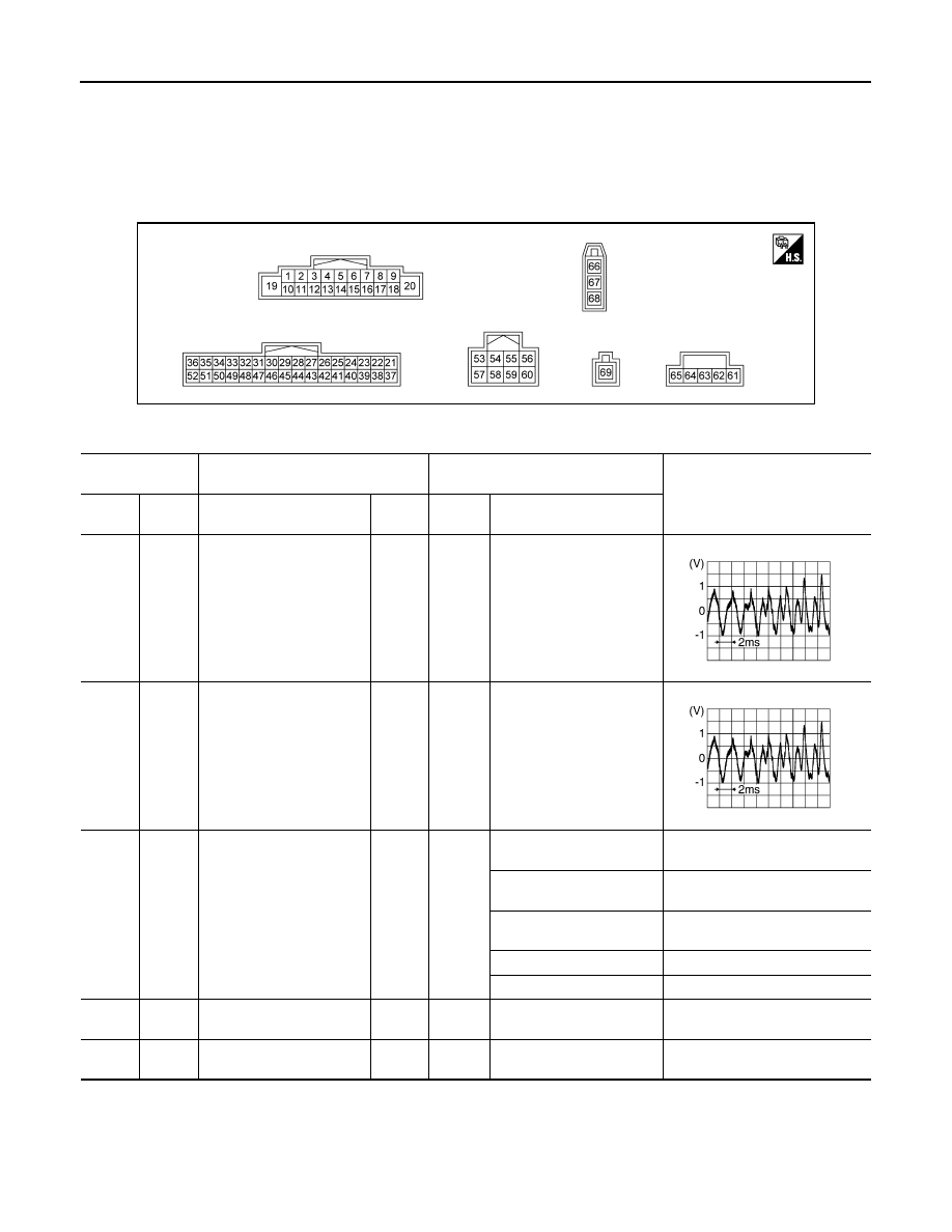
Reference Value
INFOID:0000000012202458
TERMINAL LAYOUT
PHYSICAL VALUES
JSNIA8066ZZ
Terminal
(Wire color)
Description
Condition
Reference value
(Approx.)
+
–
Signal name
Input/
Output
Ignition
switch
Operation
2
(W)
3
(GR)
Sound signal front speaker
LH
Output
ON
Sound output
4
(LG)
5
(V)
Sound signal rear speaker
LH
Output
ON
Sound output
6
(G)
15
(V)
Steering switch signal A
Input
Ignition
switch
ON
Keep pressing SOURCE
switch.
0 V
Keep pressing SEEK UP
switch.
1.0 V
Keep pressing SEEK
DOWN switch.
2.0 V
Keep pressing TEL switch.
3.0 V
Except for above.
5.0 V
7
(L)
Ground ACC power supply
Input
ACC
—
Battery voltage
8
(GR)
Ground
Illumination control signal
ground
—
ON
—
0 V
SKIB3609E
SKIB3609E