Nissan Tiida C11. Manual - part 871


  Главная      Nissan     Nissan Tiida C11 - Service Manual


поиск по сайту            


содержание   ..  869  870  871  872   ..


Nissan Tiida C11. Manual - part 871


HAC-148

< COMPONENT DIAGNOSIS >

[AUTO AIR CONDITIONER (W/O NAVI)]

PTC HEATER CONTROL SYSTEM

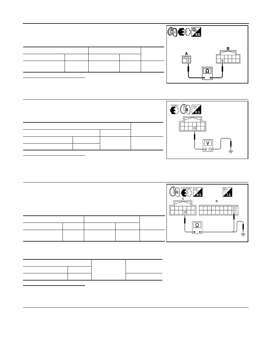
Check continuity between water temperature sensor harness con-
nector M64 (A) terminal 2 and PTC control unit harness connector
M84 (B) terminal 8.

Is the inspection result normal

YES

>> GO TO 16.

NO

>> Repair harness or connector.

16.

CHECK VOLTAGE BETWEEN PTC CONTROL UNIT AND GROUND

1.

Turn ignition switch ON.

2.

Check voltage between PTC heater harness connector M84 ter-
minal 10 and ground.

Is the inspection result normal

YES

>> 1.

If equipped with manual transmission, GO TO 22.

2.

If equipped with automatic transmission, GO TO 24.

NO

>> GO TO 17.

17.

CHECK CIRCUIT CONTINUITY BETWEEN PTC CONTROL UNIT AND FRONT AIR CONTROL

1.

Turn ignition switch OFF.

2.

Disconnect front air control and PTC control unit connector.

3.

Check continuity between PTC control unit harness connector
M84 (A) terminal 10 and front air control harness connector M85
(B) terminal 9.

4.

Check continuity between PTC control unit harness connector
M84 (A) terminal 10 and ground.

Is the inspection result normal

YES

>> GO TO 18.

NO

>> Repair harness or connector.

18.

CHECK VOLTAGE BETWEEN AMBIENT SENSOR AND GROUND

A

B

Continuity

Connector

Terminal

Connector

Terminal

Water temperature 

sensor: M64

2

PTC control unit: 

M84

8

Yes

SJIA0923E

Terminals

Voltage

(Approx.)

(+)

(

)

Connector

Terminal

Ground

5V

PTC control unit: M84

10

AWIIA0521ZZ

A

B

Continuity

Connector

Terminal

Connector

Terminal

PTC control unit: M84

10

Front air control: 

M85

9

Yes

A

Ground

Continuity

Connector

Terminal

PTC control unit: M84

10

No

AWIIA0525ZZ

PTC HEATER CONTROL SYSTEM

HAC-149

< COMPONENT DIAGNOSIS >

[AUTO AIR CONDITIONER (W/O NAVI)]

C

D

E

F

G

H

J

K

L

M

A

B

HAC

N

O

P

1.

Turn ignition switch OFF.

2.

Disconnect ambient sensor connector E60.

3.

Turn ignition switch ON.

4.

Check voltage between ambient sensor harness connector E60
terminal 2 and ground.

Is the inspection result normal?

YES

>> GO TO 19.

NO

>> GO TO 21.

19.

CHECK CIRCUIT CONTINUITY BETWEEN AMBIENT SENSOR AND FRONT AIR CONTROL 

1.

Turn ignition switch OFF.

2.

Disconnect front air control connector M51.

3.

Check continuity between ambient sensor harness connector
E60 (A) terminal 1 and front air control harness connector M51
(B) terminal 33.

Is the inspection result normal?

YES

>> GO TO 20.

NO

>> Repair harness or connector.

20.

CHECK AMBIENT SENSOR

Refer to 

HAC-151, "PTC HEATER (300 WATT) : PTC Heater (300 Watt) Component Inspection"

.

Is the inspection result normal?

YES

>> 1.

Replace front air control. Refer to XX.

2.

Go to self-diagnosis 

HAC-213, "Front Air Control Self-Diagnosis"

 and perform self-diagnosis

STEP-2. Confirm that code No. 20 is displayed.

NO

>> 1.

Replace ambient sensor. Refer to XX.

2.

Go to self-diagnosis 

HAC-213, "Front Air Control Self-Diagnosis"

 and perform self-diagnosis

STEP-2. Confirm that code No. 20 is displayed.

21.

CHECK CIRCUIT CONTINUITY BETWEEN AMBIENT SENSOR AND FRONT AIR CONTROL

1.

Turn ignition switch OFF.

2.

Disconnect front air control connector M51.

3.

Check continuity between ambient sensor harness connector
E60 (A) terminal 2 and front air control harness connector M51
(B) terminal 30.

4.

Check continuity between ambient sensor harness connector
E34 (A) terminal 2 and ground.

Terminals

Voltage

(Approx.)

(+)

(

)

Connector

Terminal 

Ground

Ambient sensor: 

E60

2

5V

AWIIA0307ZZ

A

B

Continuity

Connector

Terminal

Connector

Terminal

Ambient sensor: 

E60

1

Front air control: 

M51

33

Yes

AWIIA0308ZZ

A

B

Continuity

Connector

Terminal

Connector

Terminal

Ambient sensor: 

E60

2

Front air control: 

M51

30

Yes

AWIIA0309ZZ

HAC-150

< COMPONENT DIAGNOSIS >

[AUTO AIR CONDITIONER (W/O NAVI)]

PTC HEATER CONTROL SYSTEM

Is the inspection result normal?

YES

>> 1.

Replace front air control. Refer to XX.

2.

Go to self-diagnosis 

HAC-213, "Front Air Control Self-Diagnosis"

 and perform self-diagnosis

STEP-2. Confirm that code No. 20 is displayed.

NO

>> Repair harness or connector.

22.

CHECK ENGINE RPM SIGNAL (MANUAL TRANSMISSION)

1.

Reconnect PTC control unit.

2.

Start the engine.

3.

Check voltage between PTC control unit harness connector
M84 terminal 4 and ground.

Is the inspection result normal

YES

>> GO TO 24.

NO

>> GO TO 23.

23.

CHECK CONTINUITY OF ENGINE RPM CIRCUIT BETWEEN FRONT AIR CONTROL AND PTC CON-

TROL UNIT (MANUAL TRANSMISSION)

1.

Turn ignition switch OFF.

2.

Disconnect ECM and PTC control unit connector.

3.

Check continuity between PTC control unit harness connector
M84 (A) terminal 4 and ECM harness connector F10 (B) termi-
nal 13.

4.

Check continuity between PTC control unit harness connector
M84 (A) terminal 4 and ground.

Is the inspection result normal

YES

>> Replace ECM. Refer to XX.

NO

>> Repair harness or connector.

24.

CHECK BCM INPUT (FAN ON) SIGNAL

A

Ground

Continuity

Connector

Terminal

Ambient sensor: 

E60

2

No

Terminals

Voltage

(Approx.)

(+)

(

)

Connector

Terminal

Ground

PTC control unit: M84

4

4.2V

SJIA0924E

A

B

Continuity

Connector

Terminal

Connector

Terminal

PTC control unit: M84

4

ECM: F10

13

Yes

A

Ground

Continuity

Connector

Terminal

PTC control unit: M84

4

No

SJIA0925E

PTC HEATER CONTROL SYSTEM

HAC-151

< COMPONENT DIAGNOSIS >

[AUTO AIR CONDITIONER (W/O NAVI)]

C

D

E

F

G

H

J

K

L

M

A

B

HAC

N

O

P

1.

Turn blower control dial to "1" position.

2.

Confirm fan on signal between PTC control unit harness con-
nector M84 terminal 11 and ground using oscilloscope.

Is the inspection result normal

YES

>> Replace PTC control unit.

NO

>> GO TO 25.

25.

CHECK CIRCUIT CONTINUITY BETWEEN BCM AND PTC CONTROL UNIT

1.

Turn ignition switch OFF.

2.

Disconnect BCM connector and PTC control unit connector.

3.

Check continuity between BCM harness connector M19 (A) ter-
minal 50 and PTC control unit harness connector M84 (B)   ter-
minal 11.

4.

Check continuity between PTC control unit harness connector
M84 (A) terminal 11 and ground.

Is the inspection result normal

YES

>> Replace BCM. Refer to XX.

NO

>> Repair harness or connector.

PTC HEATER (300 WATT) : PTC Heater (300 Watt) Component Inspection

INFOID:0000000001682709

COMPONENT INSPECTION

Ambient Sensor

Terminals

Voltage

(Approx.)

(+)

(-)

Connector

Terminal

PTC control 

unit: M84

11

Ground

AWIIA0460ZZ

ZJIA0583J

A

B

Continuity

Connector

Terminal

Connector

Terminal

BCM: M19

50

PTC control unit: 

M84

11

Yes

A

Ground

Continuity

Connector

Terminal

PTC control unit: M84

11

No

AWIIA0461ZZ


содержание   ..  869  870  871  872   ..