содержание .. 867 868 869 870 ..
Nissan Tiida C11. Manual - part 869
HAC-140
< COMPONENT DIAGNOSIS >
[AUTO AIR CONDITIONER (W/O NAVI)]
INTAKE SENSOR
1.
Turn ignition switch OFF.
2.
Disconnect front air control connector M51.
3.
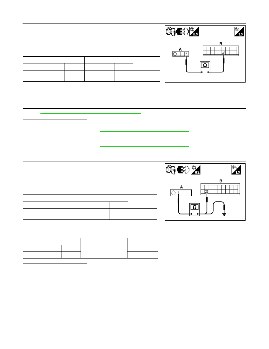
Check continuity between intake sensor harness connector M92
(A) terminal 2 and front air control harness connector M51 (B)
terminal 33.
Is the inspection result normal?
YES
>> GO TO 3.
NO
>> Repair harness or connector.
3.
CHECK INTAKE SENSOR
HAC-140, "Intake Sensor Component Inspection"
.
Is the inspection result normal?
YES
>> 1.
Replace front air control. Refer to XX.
2.
HAC-98, "Front Air Control Self-Diagnosis"
STEP-2. Confirm that code No. 20 is displayed.
NO
>> 1.
Replace intake sensor. Refer to XX.
2.
HAC-98, "Front Air Control Self-Diagnosis"
STEP-2. Confirm that code No. 20 is displayed.
4.
CHECK CIRCUIT CONTINUITY BETWEEN INTAKE SENSOR AND FRONT AIR CONTROL
1.
Turn ignition switch OFF.
2.
Disconnect front air control connector M51.
3.
Check continuity between intake sensor harness connector M92
(A) terminal 1 and front air control harness connector M51 (B)
terminal 29.
4.
Check continuity between intake sensor harness connector M92
(A) terminal 1 and ground.
Is the inspection result normal?
YES
>> 1.
Replace front air control. Refer to XX.
2.
HAC-98, "Front Air Control Self-Diagnosis"
STEP-2. Confirm that code No. 20 is displayed.
NO
>> Repair harness or connector.
Intake Sensor Component Inspection
INFOID:0000000001547445
COMPONENT INSPECTION
Intake Sensor
A
B
Continuity
Connector
Terminal
Connector
Terminal
Intake sensor: M92
2
Front air con-
trol: M51
33
Yes
SJIA0826E
A
B
Continuity
Connector
Terminal
Connector
Terminal
Intake sensor: M92
1
Front air control:
M51
29
Yes
A
Ground
Continuity
Connector
Terminal
Intake sensor: M92
1
No
SJIA0827E