содержание .. 842 843 844 845 ..
Nissan Tiida C11. Manual - part 844
HAC-40
< COMPONENT DIAGNOSIS >
[MANUAL AIR CONDITIONER]
PTC HEATER CONTROL SYSTEM
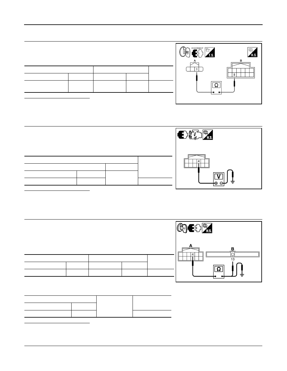
19.
CHECK CIRCUIT CONTINUITY BETWEEN AMBIENT TEMPERATURE SENSOR AND PTC CONTROL
UNIT
Check continuity between ambient temperature sensor harness con-
nector M60 (A) terminal 3 and PTC control unit harness connector
M84 (B) terminal 8.
Is the inspection result normal
YES
>> 1.
If equipped with manual transmission, GO TO 20.
2.
If equipped with automatic transmission, GO TO 22.
NO
>> Repair harness or connector.
20.
CHECK ENGINE RPM SIGNAL (MANUAL TRANSMISSION)
1.
Reconnect PTC control unit.
2.
Start the engine.
3.
Check voltage between PTC control unit harness connector
M84 terminal 4 and ground.
Is the inspection result normal
YES
>> GO TO 22.
NO
>> GO TO 21.
21.
CHECK CONTINUITY OF ENGINE RPM CIRCUIT BETWEEN FRONT AIR CONNTROL AND PTC CON-
TROL UNIT (MANUAL TRANSMISSION)
1.
Turn ignition switch OFF.
2.
Disconnect ECM and PTC control unit connector.
3.
Check continuity between PTC control unit harness connector
M84 (A) terminal 4 and ECM harness connector F10 (B) termi-
nal 13.
4.
Check continuity between PTC control unit harness connector
M84 (A) terminal 4 and ground.
Is the inspection result normal
YES
>> Replace ECM. Refer to XX.
NO
>> Repair harness or connector.
22.
CHECK BCM INPUT (FAN ON) SIGNAL
A
B
Continuity
Connector
Terminal
Connector
Terminal
Ambient temperature
sensor: M64
3
PTC control unit:
M84
8
Yes
AWIIA0464ZZ
Terminals
Voltage
(Approx.)
(+)
(
−
)
Connector
Terminal
Ground
PTC control unit: M84
4
4.2V
SJIA0924E
A
B
Continuity
Connector
Terminal
Connector
Terminal
PTC control unit: M84
4
ECM: F10
13
Yes
A
Ground
Continuity
Connector
Terminal
PTC control unit: M84
4
No
SJIA0925E