содержание .. 840 841 842 843 ..
Nissan Tiida C11. Manual - part 842
HAC-32
< COMPONENT DIAGNOSIS >
[MANUAL AIR CONDITIONER]
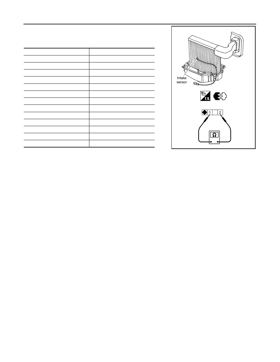
INTAKE SENSOR
After disconnecting intake sensor connector M42, measure resis-
tance between terminals 1 and 2 at sensor side, using the table
below.
If NG, replace intake sensor. Refer to XXXX.
Temperature
°
C (
°
F)
Resistance k
Ω
−
15 (5)
12.34
−
10 (14)
9.62
−
5 (23)
7.56
0 (32)
6.00
5 (41)
4.80
10 (50)
3.87
15 (59)
3.15
20 (68)
2.57
25 (77)
2.12
30 (86)
1.76
35 (95)
1.47
40 (104)
1.23
45 (113)
1.04
SJIA0828E