содержание .. 838 839 840 841 ..
Nissan Tiida C11. Manual - part 840
HAC-24
< COMPONENT DIAGNOSIS >
[MANUAL AIR CONDITIONER]
MAGNET CLUTCH
NG
>> Perform trouble diagnosis for unusual pressure. Refer to
HAC-77, "Trouble Diagnoses for
6.
CHECK MAGNET CLUTCH CIRCUIT
Perform diagnostic procedure for the magnetic clutch. Refer to "DIAGNOSTIC PROCEDURE FOR MAGNET
CLUTCH".
OK or NG
OK
>> If the symptom still exists, perform a complete operational check. Refer to
. If other symptoms exist, refer to
HAC-5, "How to Perform Trouble Diagnosis For Quick
NG
>> Repair as necessary.
Magnet Clutch Diagnosis Procedure
INFOID:0000000001547071
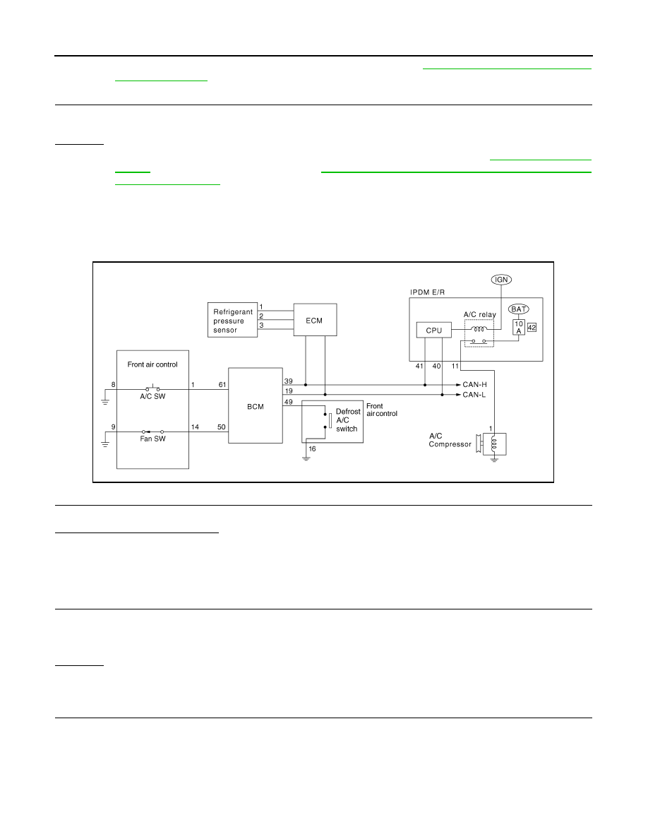
DIAGNOSTIC PROCEDURE FOR MAGNET CLUTCH
SYMPTOM: Magnet clutch does not engage in A/C, defrost/foot, or defrost mode.
1.
PERFORM AUTO ACTIVE TEST
Refer to XX.
Does the magnet clutch operate?
YES
>> GO TO 5.
NO
>>
Check 10A fuse (No. 42, located in the IPDM E/R).
• If fuse is OK, GO TO 2.
• If fuse is NG, replace fuse and check harness for short circuit. Repair or replace if necessary.
2.
CHECK POWER SUPPLY FOR IPDM E/R
Check power supply to 10A fuse (No. 42 located in the IPDM E/R).
OK or NG
OK
>> GO TO 3.
NG
>> Check harness for open circuit. Repair or replace if necessary.
3.
CHECK POWER SUPPLY FOR A/C COMPRESSOR
AWIIA0352GB
:Battery voltage should exist