содержание .. 751 752 753 754 ..
Nissan Tiida C11. Manual - part 753
EXL-10
< FUNCTION DIAGNOSIS >
HEADLAMP (XENON)
HEADLAMP (XENON)
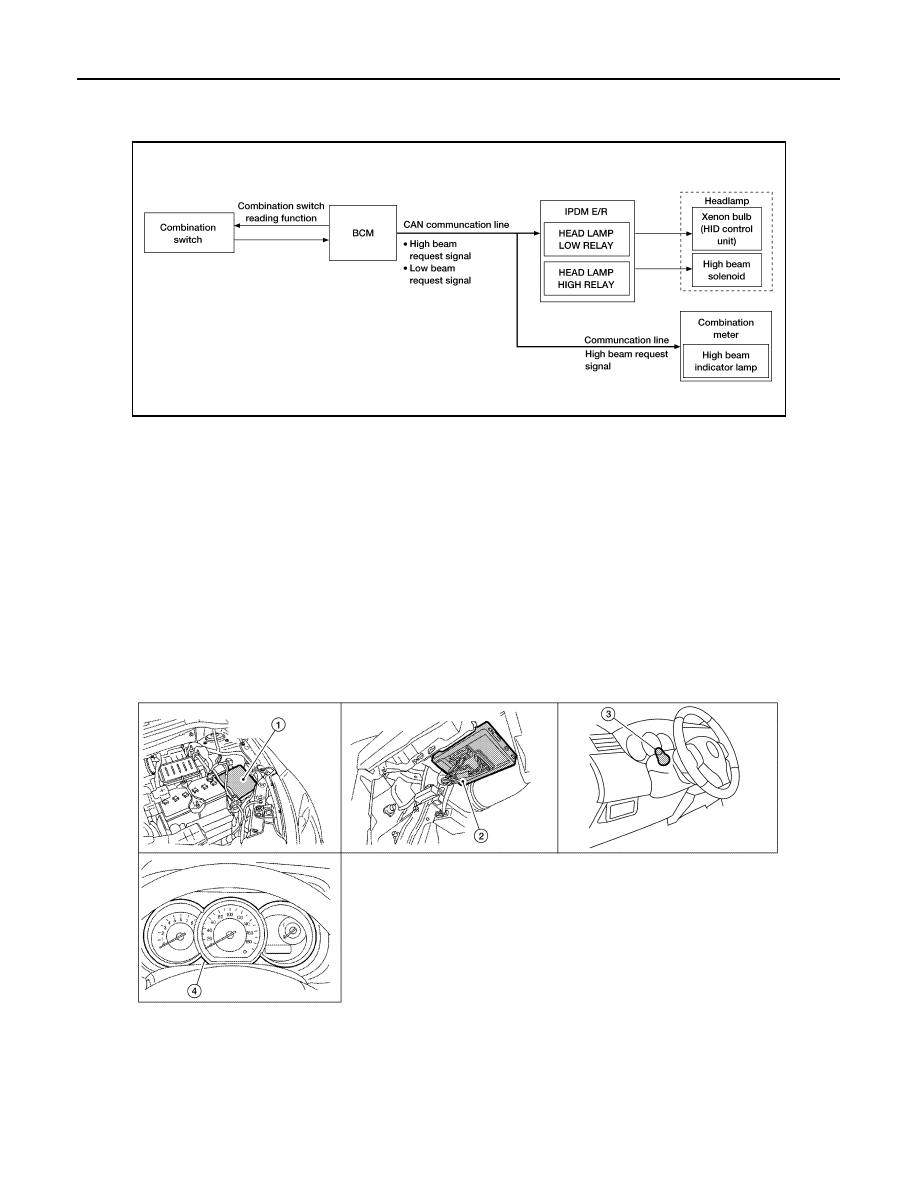
System Diagram
INFOID:0000000001527648
System Description
INFOID:0000000001527649
A mobile valve shade type xenon headlamp is used. The xenon headlamp uses one xenon bulb each on the
LH and RH side. The xenon headlamp switches between high beam and low beam by using a high beam
solenoid to move the mobile valve shade over the xenon bulb.
Control of the headlamp system is dependent upon the position of the lighting switch (combination switch).
When the lighting switch is placed in the 2nd position, the BCM (body control module) receives input request-
ing the headlamps to illuminate. This input is then communicated to the IPDM E/R (intelligent power distribu-
tion model engine room) via the CAN communication lines. The CPU (central processing unit) of the IPDM E/
R controls the headlamp high and headlamp low relay coils. When energized, these relays direct power to the
respective headlamps, which then illuminate.
Component Parts Location
INFOID:0000000001527650
AWLIA0036GB
1.
IPDM E/R E46, E47, E48
2.
BCM M16, M17, M18, M19 (view with
glove box removed)
3.
Combination switch M28
4.
Combination meter M24
WKIA5469E