содержание .. 746 747 748 749 ..
Nissan Tiida C11. Manual - part 748
EXHAUST SYSTEM
EX-5
< ON-VEHICLE REPAIR >
[HR16DE]
C
D
E
F
G
H
I
J
K
L
M
A
EX
N
P
O
ON-VEHICLE REPAIR
EXHAUST SYSTEM
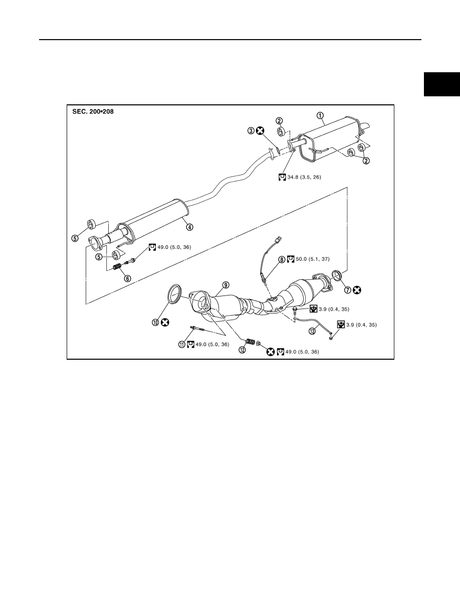
Component
INFOID:0000000001337859
Removal and Installation
INFOID:0000000001337860
REMOVAL
CAUTION:
• Be sure to use genuine NISSAN exhaust system parts or equivalents which are specially designed
for heat resistance, corrosion resistance and shape.
• Perform the operation with the exhaust system fully cooled down because the system will be hot
just after the engine stops.
• Be careful not to cut your hand on heat insulator edge.
1.
Disconnect harness connector of heated oxygen sensor 2.
• Using Tool, remove heated oxygen sensor 2.
CAUTION:
Be careful not to damage heated oxygen sensor 2.
a.
1.
Main muffler
2.
Mounting rubber
3.
Ring gasket
4.
Center muffler
5.
Mounting rubber
6.
Spring
7.
Seal bearing
8.
Heated oxygen sensor 2
9.
Exhaust front tube
10. Seal bearing
11. Stud bolt
12. Spring
13. Ground cable
WBIA0844E
Tool number
: KV10114400 (J-38365)