содержание .. 714 715 716 717 ..
Nissan Tiida C11. Manual - part 716
EM-216
< DISASSEMBLY AND ASSEMBLY >
[MR18DE]
ENGINE UNIT
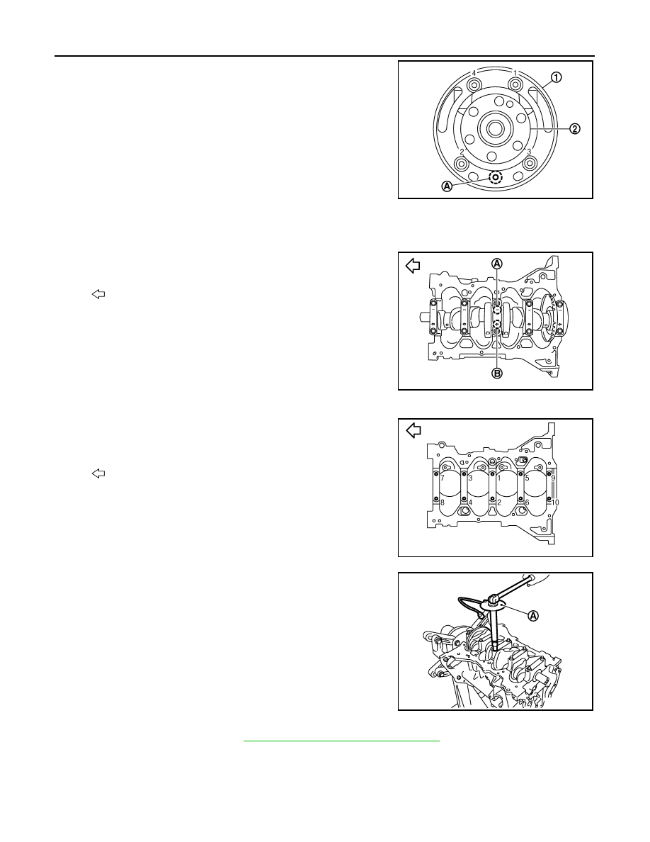
9.
Position crankshaft (2) and signal plate (1) using a dowel pin
(service part), and tighten bolts in numerical order as shown.
NOTE:
Dowel pin of crankshaft and signal plate is provided as a set for
each.
10. Tighten bolts in numerical order as shown.
11. Remove dowel pin. (service parts)
CAUTION:
Be sure to remove dowel pin.
12. Install crankshaft to cylinder block.
• While turning crankshaft by hand, make sure that it turns smoothly.
13. Install main bearing caps referring to the journal No. stamp (A)
and front mark (B) as shown.
NOTE:
Main bearing cap cannot be replaced as a single part, because it
is machined together with cylinder block.
14. Apply new engine oil to threads and seat surfaces of bolts.
15. Tighten main bearing cap bolts in two steps.
NOTE:
Tighten main bearing cap bolts in numerical order as shown:
• After installing bolts, make sure that crankshaft can be rotated smoothly by hand.
• Check crankshaft end play. Refer to
EM-219, "Inspection After Disassembly"
16. Using snap ring pliers, install new snap ring to the groove of the piston rear side.
• Insert it fully into groove to install.
17. Assemble piston to connecting rod.
A
: Dowel pin hole
PBIC3238J
: Engine front
PBIC3239J
: Engine front
Step 1
: 34.3 N·m (3.5 kg-m, 25 ft-lb)
Step2
60
°
clockwise
PBIC3235J
Tool number
: KV10112100 (BT-8653-A)
PBIC3240J