содержание .. 664 665 666 667 ..
Nissan Tiida C11. Manual - part 666
EM-16
< ON-VEHICLE MAINTENANCE >
[HR16DE]
DRIVE BELTS
CAUTION:
• When the lock nut is loosened excessively, the idler pulley tilts and the correct tension adjust-
ment cannot be performed. Never loosen it excessively (more than 45 degrees).
• Put a matching mark on the lock nut, and check turning angle with a protractor. Never visually
check the tightening angle.
2.
Adjust the belt tension by turning the adjusting bolt.
CAUTION:
• When checking immediately after installation, first adjust it to the specified value. Then, after
turning crankshaft two turns or more, re-adjust to the specified value to avoid variation in deflec-
tion between pulleys.
• When the tension adjustment is performed, the lock nut should be in the condition at step“2”. If
the tension adjustment is performed when the lock nut is loosened more than the standard, the
idler pulley tilts and the correct tension adjustment cannot be performed.
3.
Tighten the idler pulley lock nut.
Removal and Installation
INFOID:0000000001381386
REMOVAL
1.
Loosen the idler pulley lock nut (A), and then adjust the belt ten-
sion by turning the adjusting bolt (B).
2.
Remove drive belt.
INSTALLATION
1.
Pull the idler pulley in the loosening direction, and then tempo-
rarily tighten the idler pulley lock nut (A) to the following torque.
NOTE:
Do not move the lock nut from the tightened position. Proceed to step “2”.
2.
Install the drive belt to each pulley.
CAUTION:
• Make sure that there is no oil, grease, or coolant, etc. in pulley grooves.
• Make sure that the belt is securely inside the groove on each pulley.
3.
Adjust drive belt tension by turning the adjusting bolt. Refer to
.
CAUTION:
Idler pulley lock nut
: 34.8 N·m (3.5 kg-m, 26 ft-lb)
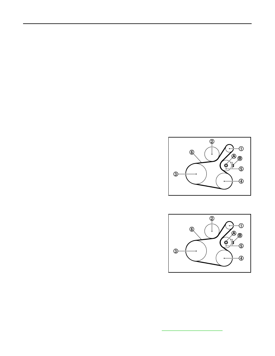
1
: Generator
2
: Water pump
3
: Crankshaft pulley
4
: A/C compressor (with A/C models)
: Idler pulley (without A/C models)
5
: Idler pulley
6
: Drive belt
PBIC3643E
1
: Generator
2
: Water pump
3
: Crankshaft pulley
4
: A/C compressor (with A/C models)
: Idler pulley (without A/C models)
5
: Idler pulley
6
: Drive belt
B
: Adjusting bolt
Idler pulley lock nut
: 4.4 N·m (0.45 kg-m, 39 in-lb)
PBIC3643E